Practical Process Control Part 7: Parameters for Designing Liquid Level Controllers
Myke King continues his detailed series on process control, seeking to inspire chemical engineers to exploit untapped opportunities for improvement
WHY the focus on liquid level control? It's not like we’re planning articles dedicated to flow, pressure, or temperature control. The first part of the answer is that liquid level is the main example of an integrating process. When we perform a step test, by changing the manipulated flow, the level will not reach a new steady state. We therefore need another way of determining process gain. Second, we might wish to apply very different controller tuning objectives. For some vessels, instead of tight control, we might wish to install averaging level control that utilises the surge capacity. Finally, most control systems support a range of modifications to the PID algorithm, designed specifically for averaging level control.
Tight versus average
Tight level control is installed where maintaining the level at set-point is more important than maintaining the manipulated flow as constant as possible. For example, we would not want to risk a high liquid level in the suction (knock-out) drum of a compressor. The liquid is likely to be routed to some recovery system that can readily absorb rapid changes in flow. Tight level control is also required on steam drums. We would not want to risk a low or high water level and there is little advantage in gradually changing the flow of boiler feed water from storage. Other examples include the level control at the base of some types of distillation columns – particularly those with a kettle-type reboiler that must always be kept totally immersed.
Averaging control, by contrast, is applicable where we are prepared to allow the level to deviate significantly from its set-point for long periods – provided it does not reach alarm limits. The most common situation is on feed surge drums. Installing tight control wastes the investment in the drum.
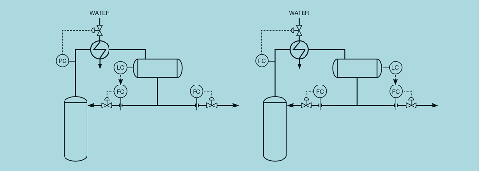
But surge capacity can exist in other parts of the process, almost by accident. Consider the two possible level control configurations for a distillation column reflux drum, shown in Figure 1. The scheme on the left is known as the material balance scheme in which drum level is controlled by manipulating reflux. Should we wish to change the overhead composition, we would adjust the product draw flow. In itself, it has no impact on the column; it is the correction that the level controller then makes to the reflux flow that changes the composition. We would want the reflux to change as quickly as possible and so would install tight level control.
The scheme on the right is known as the energy balance scheme in which the level is controlled by manipulating the product draw. Now, to change the composition, we can directly adjust the reflux. It leaves us free to choose what type of level control is appropriate. In many cases, the overhead product will be routed directly to another part of the process – maybe to another column or a reactor. In which case, averaging level control would help smooth out feed flow disturbances. The reflux drum, although not intended as such, has become the feed surge drum to the downstream process.
As we’ll soon see, tuning for averaging control is technically quite simple. The main issue is likely to be operator acceptance. Operators like to see all controllers at set-point, preferably trending as straight lines. They might be concerned by a level not quickly returning to set-point. The control engineer is likely to have to put significant effort into gaining acceptance – possibly by initially placing tight limits on the level, relaxing them as the controller proves reliable and beneficial.
Direct versus cascade
Before tuning the controller we must decide whether the control should be direct, with the level controller manipulating the control valve, or cascade, with the level controller manipulating the set-point of the flow controller. See Figure 2. If we require tight control, there is little advantage in the cascade approach. Indeed, we might value the increased reliability of a scheme that would not be affected by a problem arising with the flow measurement. However, for averaging control, the cascade has an advantage. Remembering that we want to keep the downstream flow as steady as possible, consider the effect of a pressure disturbance. If the drum pressure increases (or the downstream pressure decreases) there will be an initial increase in the liquid flow. If we have the direct acting scheme in place, we must install tight level control to correct the flow imbalance across the drum quickly and so maintain a constant flow.
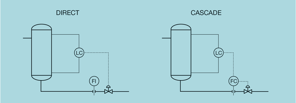
Now consider an increase in the upstream flow. With the necessary tight level control, this increase will be immediately reflected in the downstream flow. We are not able to use the surge capacity. With the cascade scheme in place, the flow controller will deal quickly with pressure changes, leaving us free to use averaging level control to minimise the effect of flow changes.
Vessel working volume
Vessel level measurements are rarely displayed in engineering units; more usually they display in % of instrument range. To calculate controller tuning we need to convert the level measurement to volumetric units (eg, m3 or litres). To do this we need to quantify the parameter V – the working volume of the vessel. This is not the total volume, but the volume that exists between 0 and 100% of the level range. It can, of course, be calculated from the vessel dimensions. But this calculation, as we’ll show in the next article, is complex and relies on equipment records being readily available and up to date. A better approach is to conduct a simple plant test – equivalent to the step-testing we complete for other controllers.
Starting at steady state, the test comprises adjusting either the inlet or outlet flow by a small amount (Δf ). Remembering that the process is integrating, it is wise to make a very small change (so that the level moves slowly). We permit the difference to exist for a known time (t), at which point we return the flow to its starting value to prevent the level ramping too far. We record the change in liquid level (ΔL). Making sure the units of t are consistent with Δf, the working volume is then given by

If the vessel is a horizontal cylinder then there will be a non-linear relationship between liquid level and its volume. The result of the step test will vary slightly, depending on the starting and finishing level. Usually this does not present a problem. In a later article we’ll describe how vessel design can avoid this or, if already in service, how we resolve any issue.
Other parameters required
In addition to V, we require some additional parameters. The first of these is the maximum deviation (d) from set-point that we will tolerate. For tight control we choose a very small value for deviation, such as 1%. For averaging control it should ideally be the distance to the nearest alarm (in %). Low and high alarms should be equidistant from the set-point. If not, we will not be able to utilise the full surge capacity in both directions. If caution is required, to gain operator acceptance, we can choose a smaller value for d – increasing it later as confidence in the controller develops.
We need to design for the normally expected flow disturbance (f). This is the change that we expect the controller to handle. It is not the much larger value, associated with an operating problem, that we would expect to generate alarms. If the process has yet to be commissioned, a good starting value is 10% of the design flow. On an operating unit it is best estimated by looking at the trend of the flow covering a few days. Once the level controller has been commissioned, monitoring will show how closely the alarm limits are approached. If surge capacity consistently remains unused, then a smaller value for f should be used and the controller retuned. On some processes f might be relatively small for most of the time, interspersed with a very occasional large disturbance. We’ll show, in a future article, how non-linear control algorithms can be used to handle this problem.
In addition to the level measurement being in % of range, so will the output of the level controller. To convert it to engineering units we need to know the range (F) of the manipulated flow. If we have a cascade controller, this is simply the instrument range of the flow transmitter. If we have direct control, then F is the flow through the valve when fully open. If we have a flow measurement we can use historical data to assess this. Figure 3 shows a possible configuration, where the flow cannot be used as a cascade controller but does permit F to be determined.
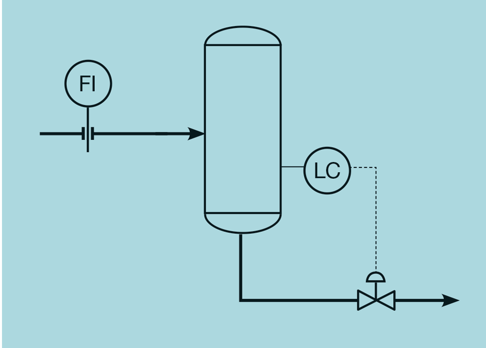
Figure 4 plots historically collected data of flow versus valve position (the scatter is partly due to the process not always being at steady state).
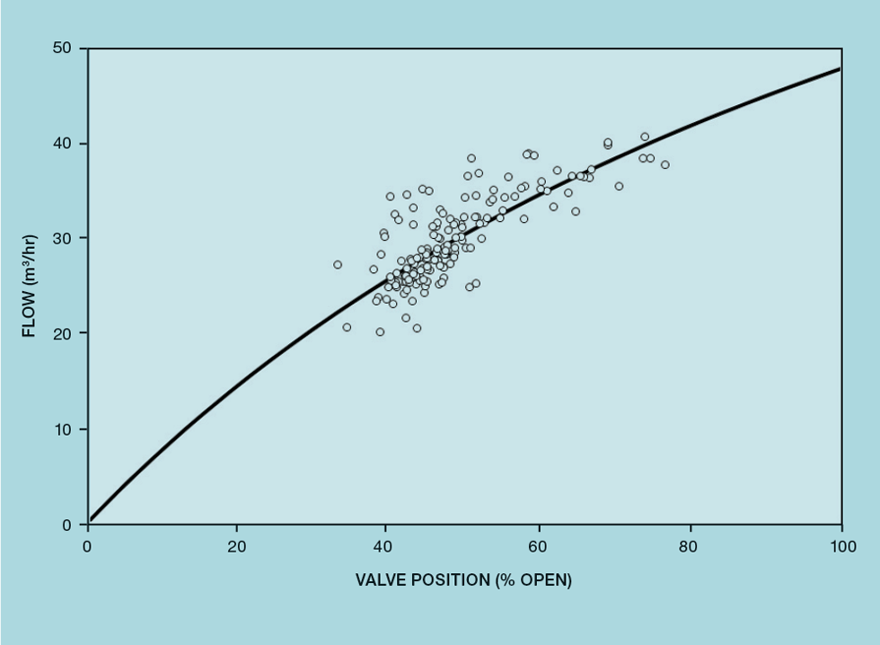
We’ll see in a later article that the flow (f) through a control valve can be related to valve position (v %) by

k is a measure of non-linearity, where 0 ≤ k < 1. Using Excel Solver, this curve can be fitted to the data to minimise the sum of the squares of the difference between the measured and predicted values for f. In this case, k is 0.43 and F is 48.2. Failing this approach, if no suitable flow measurement exists, a good estimate for F is 1.3 times the design flow.
The last parameter required is the controller scan interval (ts).
Next issue
In the next article we’ll show how the parameters we’ve collected are used to determine the tuning constants for both tight and averaging level control.
The topics featured in this series are covered in greater detail in Myke King's book, Process Control – A Practical Approach, published by Wiley in 2016.
This is the seventh in a series that provides practical process control advice on how to bolster your processes. To read more, visit the series hub at https://www.thechemicalengineer.com/tags/practical-process-control/
Disclaimer: This article is provided for guidance alone. Expert engineering advice should be sought before application.
Recent Editions
Catch up on the latest news, views and jobs from The Chemical Engineer. Below are the four latest issues. View a wider selection of the archive from within the Magazine section of this site.


