Practical Process Control Part 3: PID Algorithm Versions
Myke King continues his detailed series on process control, seeking to inspire chemical engineers to exploit untapped opportunities for improvement
The proportional-integral-derivative (PID) control algorithm has been the regulatory controller of choice for around 85 years. Initially provided by pneumatic instrumentation, and later by electronic analog, the advent of digital control systems facilitated a range of modifications. Industry has yet to fully exploit many of the valuable features now available. To understand these missed opportunities we need to develop the algorithm from first principles.
Proportional
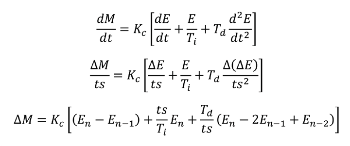
The proportional action is defined by

M is the controller output; using our example of the fired heater in last month’s article, it is the set-point of the fuel flow controller. E is the error – the deviation of the process variable (PV) from the set-point (SP). While not all control system vendors have adopted it, the now recognised definition is PV – SP. This is part of the standard published by the ISA (formerly the Instrument Society of America, now the International Society of Automation). Traditionally, text books will use SP – PV; and accounts for differences in sign when formulae from different sources are compared.
The algorithm includes the first of our three tuning parameters – the controller gain (Kc). The term C is required because it is unlikely that the error will be zero when the fuel flow is zero. It represents the flow of fuel required when the temperature is at set-point. Unfortunately C is not a constant, varying with feed rate and many other factors.
As presented, the algorithm is in the full position form. To eliminate C most control systems use the velocity form. We obtain this by differentiation.

Modern control systems are digital, operating at a fixed scan interval (ts). So we make an approximation to give the incremental form.

The main purpose of proportional control is to respond to changes in set-point. In the first control interval, after a change, ∆E will be equal to ∆SP. The controller will generate a step change in output (known as the proportional kick) equal to Kc ∆SP .

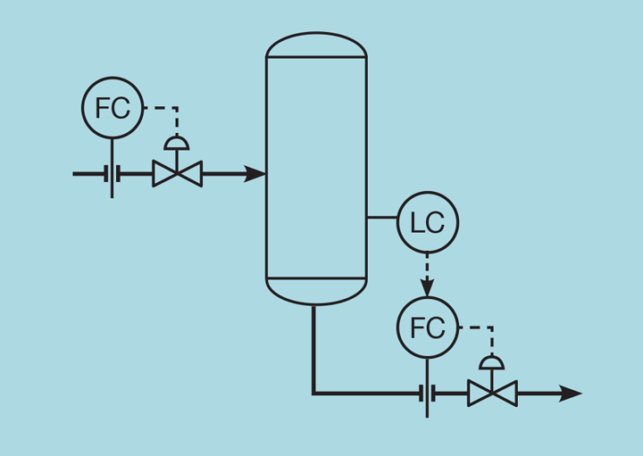
However, the PV will not reach the set-point. Instead there will be a sustained error, known as offset. To understand why this occurs, consider the level controller illustrated as Figure 1. Assume that the process is at steady state and that the controller error is zero. If the inlet flow is then increased by f then, to achieve steady state, the controller must increase the outlet flow also by f.

Integral
No matter how large we make Kc , we cannot reduce E to zero. To resolve this, we add integral action. The principle is to change M at a rate proportional to the error. In other words, M will only stop changing once the error is zero. Extending the P only controller to include integral action gives the PI controller. The amount of integral action is determined by our second tuning parameter – the integral time (Ti)

Integral action gets its name from the full position version of the algorithm. Integrating gives

Derivative
For many applications the PI algorithm will give adequate control. However, when we later come to tune the controller, we’ll show that the addition of derivative action permits Kc to be significantly increased and so resolve process disturbances more quickly. Derivative action is based on the rate of change of error. Adding it to the full position PI algorithm

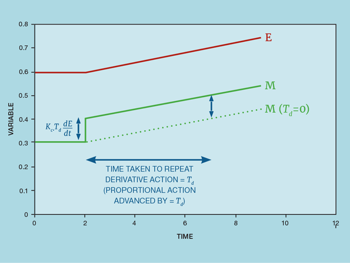
This adds our third tuning parameter – derivative time (Td). If the error is zero, no action will be taken by the proportional or integral actions. But, if it is changing quickly, an error will surely exist in the future. Derivative action anticipates this; indeed, it was once called anticipatory control. Figure 2 illustrates this. At the point where the error begins to move there is a change in the rate-of-change of error. The derivative action responds to this, making a step change in the controller output. This is then followed by the proportional action, keeping M in proportion to E. Without the derivative action the controller would respond as shown by the dashed line – eventually making the same change as the derivative action but delayed by the time Td.

Differentiating and converting to digital control

This is generally known as the ideal version of the algorithm. An alternative version adds derivative action to the PI controller by replacing E with the projected error (E’) – again anticipating the need to take corrective action.

This results in the algorithm

If derivative action is included (Td> 0) then changing either Ti or Td will now also affect the amount of proportional action. For this reason, the algorithm is described as interactive.
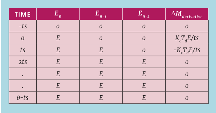
In principle, both the ideal and interactive algorithms are implemented in the control system as derived. However, the digital approximation causes a problem with the derivative action. Imagine that the process has been steady for some time and the operator causes a controller error by changing the set-point. Ignoring, for the moment, the action taken by the proportional and integral parts of the algorithm, the changes made by the derivative action are shown in Table 1. It causes a derivative spike that has a duration of one controller scan interval and a magnitude of KcTdE/ts. The value of Td will be around a minute or more, while ts will be few seconds. Td /ts will therefore be of the order of 60, so even a small change in set-point can cause M to change by more than 100%. Potentially the fuel valve could be fully open (or fully closed) for one scan interval. This may cause a serious problem in its own right, potentially causing a plant trip. Once the process deadtime has elapsed, the temperature will show a similar spike. This will be detected as an error and the controller will take corrective action causing the spike to repeat.

Recent Editions
Catch up on the latest news, views and jobs from The Chemical Engineer. Below are the four latest issues. View a wider selection of the archive from within the Magazine section of this site.


