Rules of Thumb: Vent condenser with Non-condensables
Stephen Hall discusses the golden rules for design
CONDENSERS are often used to recover chemicals that are present in vented gases. By cooling the vent stream, heat exchangers can condense a portion of constituents that have a boiling point higher than the cooled vent stream temperature. This month I am providing a simple method for estimating a condenser’s performance on vent streams that are largely composed of noncondensable gases, typically air or nitrogen.
Vent streams with noncondensables are found on dryers, vacuum systems, and nitrogen-blanketed process equipment. Condensers can recover vented solvents, protect the environment from ozone-depleting chemical emissions, or reduce the load on downstream treatment systems such as carbon adsorbers and thermal oxidisers. This article explains how to create a material balance around a condenser to estimate the composition of the chilled vent stream and the percentage of emitted components that will be condensed.
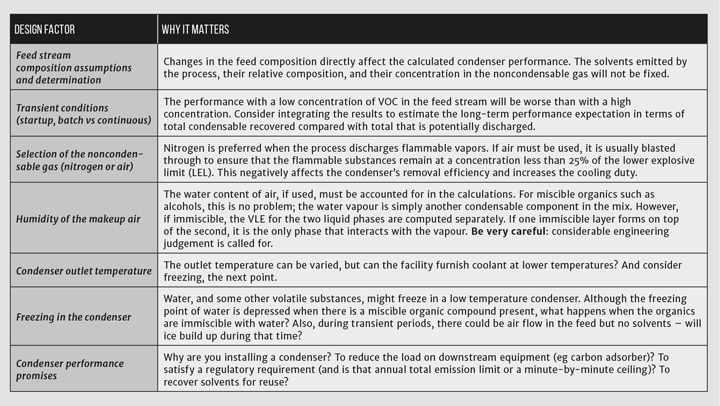
If you have access to a process simulation package, you already have the data and tools you need to perform the analysis. Your biggest challenge might be defining the feed stream to the condenser. Most vent condensers have wide variations in the composition and flow rate in the feed stream. These variations affect the performance of the condensers. They may have repercussions for adhering to emission promises, or they could have a ripple effect on additional downstream equipment such as carbon adsorbers. Although your process simulator easily solves the material balance around a condenser, you should be careful that transient and alternative cases are considered, and remember the adage “garbage in, garbage out.”
If you have access to a process simulation package, you already have the data and tools you need to perform the analysis. Your biggest challenge might be defining the feed stream to the condenser
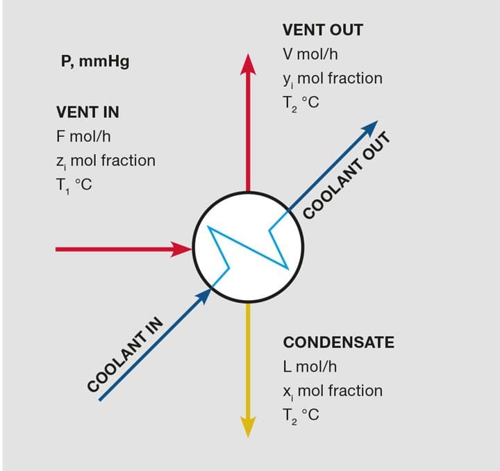
The problem is illustrated in Figure 1. Given the flow rate and composition of the feed stream, F, you can calculate the flow rates and compositions of streams V and L if the condenser operates at pressure P, and both outlet streams are at temperature T2. The feed stream temperature, T1, is not important for determining the condenser’s performance at temperature T2. But T1 is very important for designing the physical condenser because it determines the overall heat duty.
Composition at the condensing temperature
When the condenser cools the feed vapour to T2 (a temperature that is below the dew point), constituents condense, form a liquid film on the condenser’s cold surfaces, and flow out as condensate stream L. Assuming that the vapour and liquid phases come into equilibrium, stream V is saturated with molecules from the condensate in a molar concentration that is defined by Raoult’s Law (with activity coefficients, unless ideal behaviour is exhibited).
Procedure: Using an example
Granules from a crystalliser are washed with 70 vol% isopropyl alcohol (IPA), and then dried in a continuous oven. A conveyor transports the granules. Immediately after they are washed, the granules move through a heated drying chamber. The residence time in the chamber is established such that all of the alcohol and water evaporates, and the granules are dry as they exit the chamber. Nitrogen is heated and recirculated through the dryer chamber. The makeup nitrogen is controlled to establish a concentration of 10 vol% of the organic alcohol vapours in the dryer during steady-state conditions. What will a condenser on the exhaust line capture if it is operated at 5°C leaving temperature?
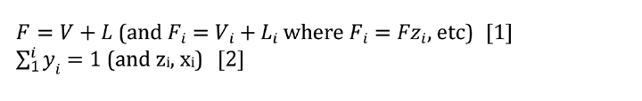
A material balance can describe this problem. Given the feed stream (F and z for each component), find V, L, xi, and yi. Fundamental Equations 1 and 2 show an easy way to solve the problem.
1. Establish the design conditions for the condenser. The calculations use molar flow rates, and the performance calculation only requires molar ratios and the exit temperature. Calculate the mole ratio of alcohol to water to find that 70 vol% IPA is 36 mol% IPA and 64 mol% water. Assuming vol% = mol% in vapour, calculate the moles of nitrogen with the following:
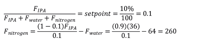
Therefore, we have the molar ratio of all of the substances in the feed. The actual flow rate is needed only when the condenser surface area is calculated, which is outside the scope of this article.
2. Calculate the mole fraction, z, of each component in the feed stream. The total moles = 360. Therefore, the mole fraction of component 1, IPA, is 36/360 = 0.10. Repeat this calculation for every component. The mole fractions sum to 1.
3. Determine the vapour pressure for each condensable component at the condensing temperature. For this example, assume that the activity coefficients are unity (ideal behaviour); these can be added later but would need to be recalculated with each iteration of the procedure because they are dependent upon the liquid phase composition.
4. Make an initial guess for the molar composition of the condensate stream. Assume that none of the nitrogen condenses (a simplifying assumption), and guess that half each of the solvents and water in the feed condenses. Calculate the mole fraction for each component in the liquid condensate at this guessed composition.
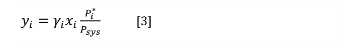
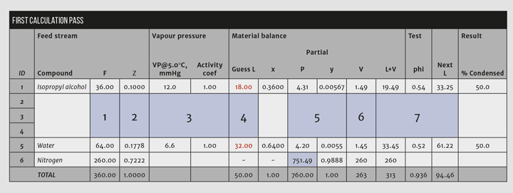
5. Use Raoult’s Law (Equation 3) to calculate the partial pressure in the vapour for each of the condensables. Then calculate the mole fractions as listed in the “y” column in Figure 2.
Key step: The partial pressure of nitrogen, the noncondensable, is calculated by subtracting the sum of the condensables from the system pressure. Doing so forces the vapour mole fractions to sum to unity.
6. From the vapour fractions, calculate the vapour molar rates. Because none of the nitrogen condenses (assumption), the quantity of nitrogen in the vent equals the quantity in the feed and the values for the condensed substances are taken as a ratio of their fraction to the nitrogen fraction. In Figure 2, the molar rate of IPA is V1 = 0.00567/0.9888*260 = 1.49.
7. Add up the guessed L and the calculated V streams. These should equal F for each substance, but, as Figure 2 shows, they do not sum correctly in the first pass. Therefore, the guessed values for L must be changed for another trial. Calculate the ratio phii= (Li+Vi)/Fi. Then calculate a new guess to Li = Li/phii. Substitute the new values into the Guess L column.
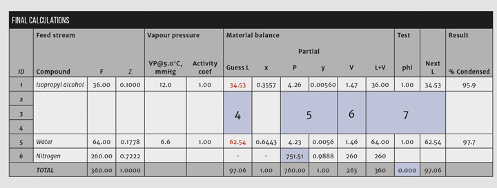
Repeat steps 5-7 until the calculation converges (see Figure 3). This should converge in a few iterations depending upon the number of condensable components and the convergence criteria. Convergence is confirmed by summing the absolute values of phi and subtracting the number of compounds as indicated in Figure 3.
Discussion
The real-world performance of a vent condenser will differ from the predictions that are indicated by the calculations. After setting up the model in Excel, you should perform a sensitivity analysis and document how the performance is likely to change as you manipulate the data inputs. Remember that these are theoretical calculations: the heat transfer coefficient and effective surface area of the condenser are fixed by the physical installation but, at the same time, they change in response to flow rates, condensate load, fouling, and other factors. Therefore, although you may model the behaviour at a certain outlet temperature from the condenser, the actual temperature could be significantly higher or lower due to the heat transfer characteristics of the equipment and differences from your design condition in the feed characteristics.
A closer look at inerting
The example problem is constructed with heated nitrogen in the drying chamber with the VOC concentration set to 10% in the feed to the condenser. Changing to an atmosphere of air greatly increases the risk for an explosion, which is usually mitigated by decreasing the concentration of the VOCs to less than 25% of the LEL.
There are challenges to using a nitrogen sweep gas. The plant operator would purchase nitrogen and install appropriate controls, such as oxygen monitors, in the space around the dryer. They would also have to configure the dryer to recirculate nitrogen through the chamber to maintain turbulent conditions that promote drying. The drying time would be higher than using an air sweep due to the high concentration of VOCs in the vapour phase.
The advantages, however, are significant. The recovery of the solvents is higher with the higher VOC concentration, in this example 96% with nitrogen but only 18% if air is used with a VOC concentration of 0.5%. Increasing the condensing temperature to 15°C has a small effect on the recovery: it is still >92%. The cooling duty with air sweep at 0.5% VOC is four times that of nitrogen with 10% VOC.
This is the 13th in a series that provides practical insights into on-the-job problems. To read more, visit the series hub at https://www.thechemicalengineer.com/tags/rules-of-thumb
Disclaimer: This article is provided for guidance alone. Expert engineering advice should be sought before application.
Recent Editions
Catch up on the latest news, views and jobs from The Chemical Engineer. Below are the four latest issues. View a wider selection of the archive from within the Magazine section of this site.


