Rules of Thumb: Jet Mixing
Stephen Hall discusses the golden rules for design
JET MIXERS use the kinetic energy in a pumped stream to blend the liquid contents of a tank or reactor. They are an alternative to motor-driven agitators. While they are commonly used on very large storage tanks where mechanical agitation is impractical, jet mixers also can be effective on small tanks. This month, I am showing you how to size a jet mixer.
The concept is simple. Liquid is pumped into a tank, below the surface, through a nozzle. The flow rate and nozzle are designed to give a high-velocity stream that drags liquid in the tank and carries it to the tank wall. The wall dissipates the stream’s remaining energy and reflects the stream back into the tank.
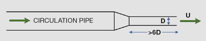
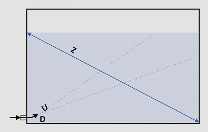
This establishes a flow pattern that is similar to the pattern that mechanical agitators create. For this article, I define a nozzle to be a plain pipe or tube where the pumped liquid is accelerated into the tank, as illustrated in Figure 1. A typical arrangement is shown in Figure 2.
Jet mixers work best with Newtonian fluids with low (<0.01 Pa-s) viscosity. You are seeking to establish flow that incorporates the entire contents of the tank. Viscous fluids require more invasive mixing for them to achieve a uniform consistency and jet mixers will probably not give satisfactory results.
The length of the path from the nozzle to the tank wall should be as long as is practicable. This will incorporate more of the contents compared to a shorter path. For large storage tanks, jet mixers are usually installed near the bottom of the side wall and aimed at the far wall just below the liquid surface. This gives a diagonal path across the centre of the tank. If the level drops below the target, however, the flow stream will hit the surface rather than the tank wall which reduces the mixing effectiveness.
Small tanks (<4 m diameter) can also be mixed with a jet mixer. The jet can be directed straight down if it is submerged and is not aimed at the tank outlet.
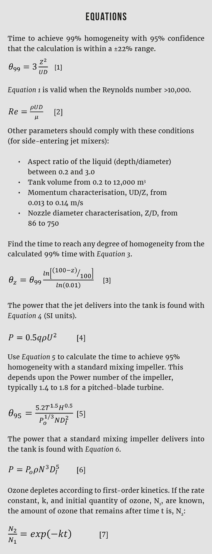
The kinetic energy and mixing momentum carried by a jet mixer are characterised by the tank’s path length, nozzle diameter, and velocity as described by Equation 1, which estimates the time needed to achieve 99% homogeneity. This correlation was developed using the longest (diagonal) path length in the test tanks, so it inherently incorporates the tank volume. The researchers positioned their jet nozzles to follow that longest path. I have no information as to how to adjust the calculation for shorter flow lengths. For example, if the nozzle is positioned in the middle of the tank, the flow length would be half of the maximum possible path. In this case, a safety factor of 25–50% can be added to the calculated mixing time to cover the uncertainty.
It is easy to adjust the calculation to estimate the time to achieve different degrees of homogeneity. Blending is a first order process, which means that the blending progresses exponentially. Use Equation 3 to adjust the calculation to a degree other than 99% homogeneity.
One way to corroborate the calculation is to estimate the power that the jet transfers to the tank. From Bernoulli’s theory and the conservation of momentum, that power is one velocity head, shown in Equation 4. Compare the jet mixing power to the power needed to achieve a similar degree of homogeneity using a standard mixer. Equations 5 and 6 give the mixing time and power input for a standard mixer. You should find that the results are similar. Of course, the total power is more than what these calculations yield. For jet mixers, power is needed to pump the fluid through piping to the jet; for standard mixers, power is lost to seal friction and gear boxes.
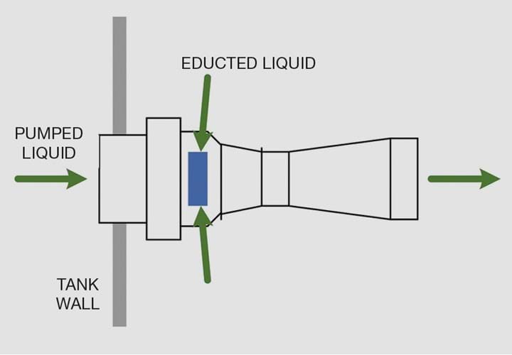
It would be remiss if I failed to mention the commercially-available jet mixing nozzles. Sold by several companies, these nozzles are submerged eductors that draw liquid from the tank into the jet stream (in a roughly 4:1 ratio), see Figure 3. This, the vendors say, enhances circulation in the tank and reduces the flow rate that is pumped into the nozzle. Eductor nozzles typically have a 2–3 bar pressure drop. It is difficult to compare their performance against the simple nozzle that I have described in this article; the vendors do not reveal fully the theory behind their formulas, which are based upon volume replacement rather than conservation of momentum. Volume replacement (tank volume divided by flow rate) is an inadequate metric for mixing time, but together with the pressure drop through the eductor nozzle, I have no doubt that the mixing effectiveness can be modelled.
Example
Problem:
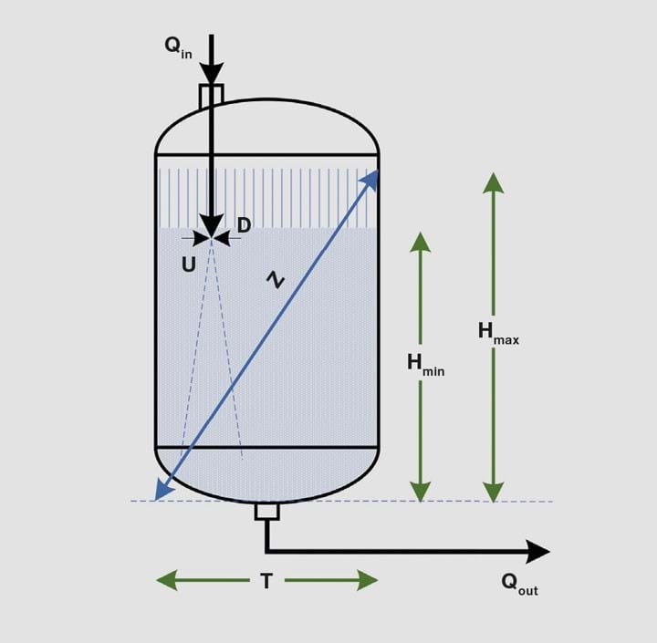
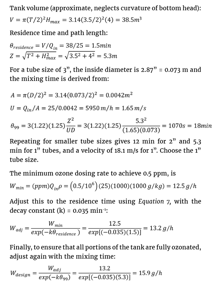
The tank illustrated in Figure 4 holds purified water for distribution to use points in a pharmaceutical manufacturing facility. To ensure that microbial growth will not proliferate, the pure water that enters the tank is dosed with ozone. Ozone (O3) decays to oxygen, following a first-order reaction kinetic. The quality assurance department requires that the ozone concentration remains above 500 ppb by weight. What is the minimum ozone addition rate? Given: T = 3.5 m; Hmax = 4 m; Hmin = 2.5 m; Qin = 25 m3/h; Qout= 25 m3/h; O3 half-life = 20 minutes. The inlet pipe size is 3”; this is hygienic tubing with sizes 1” to 3” all having wall thickness of 0.065”.
Solution:
If the tank is mixed perfectly, the minimum ozone dosing rate is calculated from the half-life and residence time. The problem, then, is to determine the jet mixer pipe diameter that gives high assurance that the mixing time is less than the residence time, or, if not, then to increase the ozone dosing rate accordingly. Use Equation 1 +22% to have a high confidence in the mixing time calculation. Add another 25% safety factor because this is a vertical jet that is submerged well below the surface of the water when the tank is full.
This approach may be too conservative, but it should withstand scrutiny.
The power delivered by the jet is:

From the pump’s perspective, this takes the form of pressure drop through the jet nozzle, which is 1 velocity head.
This is the 12th article in a series that provides practical insights into on-the-job problems. To read more, visit the series hub at https://www.thechemicalengineer.com/tags/rules-of-thumb.
Erratum: The previous version of this article misstated the mixing homogeneity predicted by Equation 1. It is 99%, not 95%. Rushton impellers have a Power number in the range of 4.5–5.0; the previous version should have given pitched-blade turbine as the example rather than Rushton. “Other parameters” in the Equations section are strictly valid only for side-entering jet mixers. Finally, the “Z” parameter was developed for side-entering jet mixers; the author is speculating that it is also applicable for top-entering mixers per the example but there is no explicit research to confirm this.
Disclaimer: This article is provided for guidance alone. Expert engineering advice should be sought before application.
Recent Editions
Catch up on the latest news, views and jobs from The Chemical Engineer. Below are the four latest issues. View a wider selection of the archive from within the Magazine section of this site.


