The Fukushima Nuclear Disaster: Then and Now
Geoff Gill reviews how the accident played out, and the huge engineering challenges involved in making the site safe
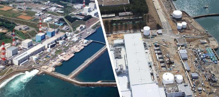
THE 11 March 2021 will mark the tenth anniversary of the Fukushima Daiichi Nuclear Power Plant accident in Japan. It was the worst nuclear accident at a nuclear power plant since the Chernobyl disaster in 1986. It was caused by a huge tsunami following a massive earthquake. The earthquake and tsunami caused great loss of life and widespread devastation in Japan.
Almost 16,000 people were killed, and more than 6,000 were injured. A comprehensive analysis of the causes and consequences of the accident has been carried out by the International Atomic Energy Agency (IAEA).1 This article gives a brief resume of the accident, its immediate impacts on the plant, and the initial efforts to protect the workers and the public. It also examines the engineering challenges in decommissioning the stricken reactors, and the need to process and ultimately dispose of the vast quantities of contaminated solid waste and water.
The accident
At the Fukushima Daiichi Nuclear Power Plant, operated by the Tokyo Electric Power Company (TEPCO), the earthquake caused damage to the electric power supply lines to the site. The largest tsunami wave, which arrived about 50 minutes after the earthquake, caused substantial destruction of the operational and safety infrastructure on the site. The combined effect led to the loss of off-site and on-site electrical power.
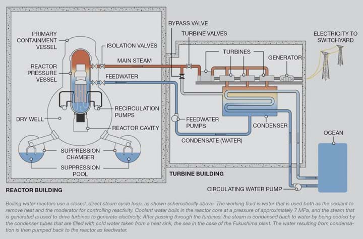
At the time of the accident, of the 6 boiling water reactors (see Figure 1) on the Fukushima site, units 1-3 were operating and units 4-6 were in planned shutdown. Despite the efforts of the operators at the plant to maintain control, the reactor cores in units 1–3 overheated, the nuclear fuel melted and the three containment vessels were breached. Hydrogen was released from the reactor pressure vessels, leading to explosions inside the reactor buildings in units 1, 3 and 4 that damaged structures and equipment and injured personnel. The first explosion occurred in unit 1 on 12 March, just over 24 hours after the earthquake. Those in units 3 and 4 followed on 14 and 15 March. Radionuclides were released from the plant to the atmosphere and were deposited on land and on the ocean. There were also direct liquid releases into the sea.
For units 1-3, TEPCO established two conditions that would define the end of the accident state, or “cold shutdown state”: achievement of significant suppression of radiological releases and steady decline of radiation dose rates; and achievement of target values for certain plant parameters. The Government of Japan and TEPCO announced that the first condition had been achieved on 19 July 2011, and on 16 December 2011, that the second condition had been achieved for these units.
Immediate emergency actions
As noted above, the earthquake and tsunami resulted in the loss of AC and DC electrical power and a huge amount of rubble. There were also aftershocks and alerts of possible further tsunamis. As a result of these factors, as well as increased radiation levels and the hydrogen explosions, and also due to the lack of detailed arrangements, the response was extremely difficult and many mitigatory actions could not be carried out in a timely manner. Workers at the site faced extremely difficult conditions; they worked longer hours and under far more tiring circumstances than would normally be expected. Management of the accident was also severely impacted. For example, the offsite emergency centre had to be relocated to another location further from the site due to increased radiation levels. This new location lacked the facilities of the established centre and led to difficulties in sharing information with other agencies.
Protection of workers and the public
1. Protecting workers at the plant
Following the earthquake, plant personnel were told via a public address system to evacuate to higher ground to protect them from the coming tsunami. This was largely successful. However, two workers who were checking equipment after the earthquake on the underground floor of the unit 4 turbine building were drowned in the flooding caused by the tsunami. Obtaining medical treatment for emergency workers with conventional injuries was made difficult because several hospitals were closed as a result of the evacuation or sheltering. Some were not prepared to treat patients who they were worried might be contaminated with radioactive material. Until primary medical care was provided on the site, emergency workers with conventional injuries were transported to one of two local hospitals for treatment.
2. Actions taken to protect the public
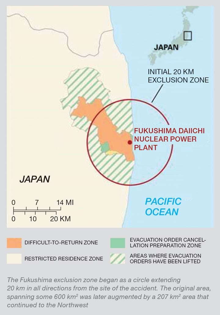
The authorities very quickly concluded that people needed evacuating from the local vicinity. This began in the evening of 11 March 2011, with the evacuation zone gradually being extended from a radius of 2 km beyond the plant to 3 km and then to 10 km. By the evening of 12 March it had been extended to 20 km (see Figure 2). Additionally, in the area within a 20–30 km radius of the plant, the public was ordered to shelter until 25 March, when the national Government recommended voluntary evacuation.
The earthquake and the tsunami caused widespread devastation. Many public facilities, homes and businesses were destroyed or damaged; access to telephones and the internet, supplies of electricity, gas, and drinking water, public transport, and the distribution of food, gasoline and heating oil were all severely disrupted. The outside temperature was low, it was raining and snowing, and heating was inadequate. This meant that many residents could not stay in the shelters for long periods without warm clothes and overcoats. These dreadful conditions affected the implementation of the protective measures required to protect people against radiation exposure. Sheltering and evacuation were particularly disruptive for around 160,000 people who were isolated from their communities and had access to only limited supplies to meet their daily needs. People were eventually relocated, but their normal living conditions were seriously affected. Employment and participation in community activities were limited. In effect, their whole way of life was massively disrupted.
Decommissioning and contaminated water management
The work to decommission the plants, deal with contaminated water and solid waste, and remediate the affected areas is immense. A “Mid-and-Long Term Roadmap”2 was developed soon after the disaster to set out how this will be achieved. Also, to facilitate decommissioning units 1-6, and dealing with contaminated water, TEPCO announced, at the end of 2013 the establishment of an internal entity: the Fukushima Daiichi Decontamination & Decommissioning Engineering Company, which commenced operations in April 2014. The entire decommissioning process will take 30–40 years, and, as noted above, the volume of tasks is gigantic. Therefore, the Government of Japan and TEPCO have prioritised each task and set the goal to achieve them. Essentially, it is a continuous risk reduction activity to protect the people and the environment from the risks associated with radioactive substances by:
- removing spent fuel and retrieval of fuel debris from the reactor buildings;
- establishing measures to deal with contaminated water; and
- establishing measures to deal with radioactive waste material.
Fuel removal from the reactor buildings
In the Fukushima Daiichi design of reactor, used and new fuel rod assemblies are stored in the upper part of the reactor. The used fuel rods are highly radioactive and continue to generate heat, and thus require continued cooling.
Depending on the degree of damage, the process of removing the fuel assemblies presents different challenges in each of the reactors. For example, one of the significant challenges is to firstly remove the large quantities of rubble caused by the hydrogen explosions. As noted above, reactors 5 and 6 were shut down at the time of the accident. The reactor cores were successfully cooled, and thus suffered no damage. Given that the conditions of the buildings and the equipment for storing the fuel are stable, and risks of causing any problem in the decommissioning process are estimated to be low compared to the other units, the fuel assemblies of units 5 and 6 continue to be safely stored in the spent fuel pool in each building for the time being. The next step will be to carefully remove the fuel from the fuel pools in units 5 and 6 without impact on fuel removal from units 1, 2 and 3.
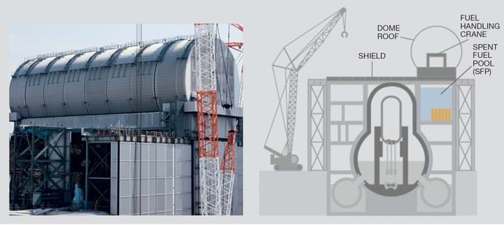
All the remaining units are going through a number of stages to achieve fuel removal. They differ slightly for each unit, but essentially the stages are: survey of internal state, removal of rubble, installation of fuel handling facility, and removal of fuel. By way of example, the position regarding unit 3 is shown in Figure 3.
At unit 3, rubble removal and other work at the upper part of the reactor building, together with installation of a cover for fuel removal was completed in February 2018.
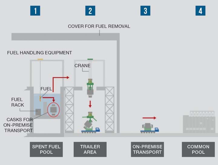
After all preparations were in place, work to remove the 566 fuel rod assemblies, including 52 non-irradiated fuel assemblies, began in April 2019. The process of fuel removal is shown diagrammatically in Figure 4.
The four stages are:
- Fuel rod assemblies stored on fuel racks in the spent fuel pool are transferred in the water one at a time to transport casks, using fuel handling equipment;
- after closing the cask cover and washing, a crane is used to lower the cask to ground level and load into a trailer;
- the cask is transported to a common pool on the site; and
- the fuel in the cask is stored in the common pool.
As of 8 January 2021, 468 assemblies including the 52 non-irradiated fuel assemblies had been removed from unit 3. Measurements of airborne contamination levels are being monitored in the surrounding environment throughout the fuel removal operations. The plan is that all fuel will have been removed from all of the reactor units by sometime during 2031.
Retrieval of fuel debris
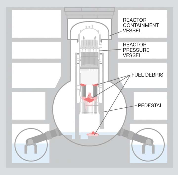
At the time of the accident, units 1–3 were operating and had fuel rods loaded in the reactors. After the accident occurred, emergency power was lost, preventing further cooling of the cores. This resulted in overheating and melting of the fuel, together with other substances. Fuel debris refers to this melted fuel and other substances, which have subsequently cooled and solidified, and, of course, still remains dangerously radioactive. This clearly poses a very complex and difficult decommissioning challenge.
Currently the state inside the containment vessel is being confirmed, and various kinds of surveys are being conducted prior to retrieval of the debris. The current aim is to begin retrieval from the first unit (unit 2), and to gradually enlarge the scale of the retrieval. The retrieved fuel debris will be stored in the new storage facility that will be constructed within the site.
The distribution of debris between the pressure and containment vessels differs in each of the 3 units. By way of example, Figure 5 shows the current position in unit 2. Large amounts of debris are located in the bottom of the pressure vessel, with little in the containment vessel.
The investigation to capture the location of fuel debris inside unit 2 was conducted from 22 March–22 July 2016. This operation applied the muon transmission method, of which effectiveness was demonstrated in its appliance for locating the debris inside unit 1. (Muon transmission method is a technique that uses cosmic ray muons to generate three-dimensional images of volumes using information contained in the Coulomb scattering of the muons.) These operations used a small device developed through a project called “Development of Technology to Detect Fuel Debris inside the Reactor’’.
Use of remote operations for decommissioning
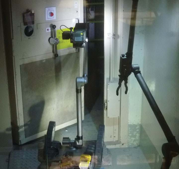
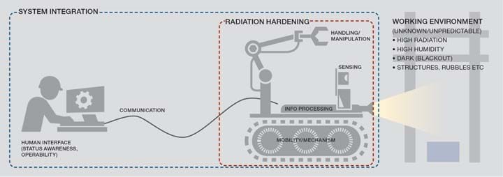
Understanding of the situation inside the stricken reactors was urgently needed following the accident in order to prevent the spread of damage and to mitigate the disaster. Tasks had to be carried out in a very complicated, difficult and unpredictable environment. In particular, the environment inside the reactor buildings reached high radiation levels due to the spread of radioactive contamination. To reduce the risk of radiation exposure to operators, remote control technologies have proved indispensable for examining the reactor buildings and subsequently for decommissioning work. Thus, remote control technology, including robot technology has been heavily utilised in response to the accident. Figure 6 shows a typical configuration of remotely-controlled robotic systems for decommissioning work.
To reduce the risk of radiation exposure to operators, remote control technologies have proved indispensable for examining the reactor buildings and subsequently for decommissioning work
The general approach to the use of remote operations in decommissioning the Fukushima Daiichi reactors has been discussed in the Japanese Journal of Applied Physics.4
Remote technologies have so far been used for surveying the inside of the reactor buildings, and to remove rubble from them. The technology is being progressively developed as new challenges are faced in the decommissioning programme. In 2016, a facility called the Naraha Center for Remote Control Technology Development (NARREC) was established by the Japan Atomic Energy Agency (JAEA) to support remote control-technology development and operational training for Fukushima Daiichi decommissioning.
Reducing the risks associated with contaminated water
Water has posed a very demanding challenge for the operators. The problem stems from groundwater flowing from the mountain side of the site toward the ocean. This flows into the reactor buildings and becomes mixed with radioactive water accumulated in the buildings, increasing the amount of contaminated water already there. The solution to the contaminated water problem is being tackled through a three-pronged approach. These are redirecting groundwater from contamination sources, removing contamination sources, and prevent leakage of contaminated water.
In order to achieve this, barriers have been installed on the land -side and sea-side of the plant. An impermeable barrier on the land-side has been achieved by freezing the ground. The frozen soil “wall” (which has a circumference of about 1,500 m) has been achieved by piping chilled brine through pipes to a depth of 30 m, which freezes the surrounding soil. On the sea-side, a wall has been constructed, consisting of 594 steel pipes (see Figure 7).
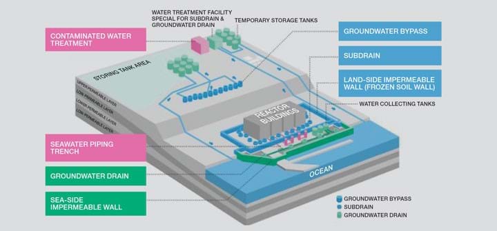
In addition to these barriers, subdrain and groundwater drainage systems have been installed. The function of the subdrain system is to prevent clean groundwater from being contaminated, by pumping it and reducing its inflow into the reactor buildings, thereby reducing the generation of contaminated water.
Multi-layered measures, including pumping up by subdrains and land-side impermeable walls, which were implemented to control the continued generation of contaminated water, reduced the groundwater inflow into buildings. Following the steady implementation of measures (groundwater bypass, subdrains, landside impermeable walls, etc), the inflow of the groundwater and rainwater into buildings reduced from approximately 350 m3/day (in 2014) to approximately 120 m3/day (in 2019), though it depends on rainfall. Subsequently, the generation of contaminated water decreased from around 470 m3/day (in 2014) to around 180 m3/day (in 2019).
Measures are continuing to further reduce the volume of contaminated water generated.
Purification treatment of contaminated water and management of treated water
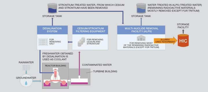
The purification process is shown diagrammatically in Figure 8.
The process of contaminated water treatment starts by separating out cesium and strontium. After that, salts are removed using desalination equipment. Part of the water treated that far is recycled for use in cooling the reactors again, and the rest proceeds through the Multi-nuclide Removal Facility, ALPS (Advanced Liquid Processing System, developed by Toshiba), where radionuclides other than tritium are separated out. ALPS consists of a pre-processing facility employing iron co-precipitation processing and carbonate precipitation processing, and a main facility with a combination of different kinds of adsorption towers. The adsorption towers in the main unit are composed of a combination of colloidal adsorption material using activated charcoal, strontium-adsorbing material, material that adsorbs both cesium and strontium, antimony-adsorbing material, silver-adsorbing material (for adsorbing iodine) and others. After treatment by ALPS, the water is stored in tanks. ALPS removes most of the radioactive materials except tritium, and radioactive materials are reduced to about one millionth, compared to the water before purification. ALPS treated water is stored in tanks located on the hill at the site (see Figure 7). The total amount of the ALPS treated water is approximately 1.21m t as of 21 May 2020. Within the scope of the current construction plan, the tanks storing the ALPS treated water are expected to be full by around the summer of 2022. A number of options for the disposition of the ALPS treated water have been identified. The option favoured by TEPCO is for sea disposal, but this option does have its detractors.
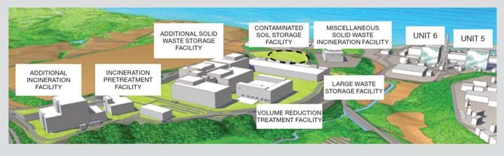
Treatment and disposal of solid radioactive waste
Waste materials resulting from the decommissioning work are sorted based on their radiation levels and are stored on the premises of the Fukushima Daiichi Nuclear Power Station. Along with strict safety measures and studies on treatment and disposal methods, a solid waste storage management plan is drawn up based on waste generation forecasts for around the next ten years, so that measures to deal with waste materials will be carried out effectively. The storage management plan is updated once a year, while reviewing the waste generation forecasts, taking account of progress of the decommissioning work. The illustration in Figure 9 shows the various facilities planned for treatment and storage of solid waste. TEPCO’s Mid and Long Term Roadmap shows all these facilities being completed by 2028. The amounts of waste generated are huge.
For example, the latest edition of the roadmap estimates the amount of solid waste which will be generated over the next 10 years to be 780,000 m3.
International safety reviews following the accident
The International Atomic Emergency Agency (IAEA) organised an International Ministerial Conference on Nuclear Safety in June 2011, which resulted in a Ministerial Declaration on Nuclear Safety. This declaration outlined a number of measures to further improve nuclear safety, emergency preparedness, and radiation protection of people and the environment worldwide. It also expressed the firm commitment of IAEA Member States to ensure that these measures were taken. In order for this to come to fruition, an Action Plan5 was prepared which defined a programme of work to strengthen the global nuclear safety framework. In the European Union, the response to the Action Plan was to formulate a number of “stress tests” to be applied to nuclear facilities. The tests, completed by licencees, involved a targeted reassessment of each station’s safety margins in light of extreme natural events, such as earthquake and tsunami. In the UK, the Office for Nuclear Regulation (ONR) required each licencee to produce a report describing the outcomes of the application of the stress tests. A significant number of improvements were identified, mainly to enhance resilience for emergency actions following events beyond the design basis or not currently foreseen, and also to enhance margin assessment methods.6
Concluding comments
The accident at Fukushima was the second major accident at a nuclear facility to be given a maximum rating of 7 on the International Nuclear Event Scale, INES. INES is a tool for communicating the safety significance of nuclear and radiological events to the public.
Up until 2011, Japan was generating some 30% of electricity from its reactors, and this was expected to increase to at least 40% by 2017. The plan is now for at most 20% by 2030, from a depleted fleet. The first two reactors restarted in August and October 2015, with a further seven having restarted since. 18 reactors are currently in the process of restart approval.
The effect on the rest of the world appears to be modest, according to some researchers.7 Following the disaster, several countries, including Germany and Switzerland decided to accelerate the closing of all their reactors. However, most countries, following a pause to review their nuclear strategies, have not made significant changes in their support for nuclear power.
This article is adapted from one published in the latest Loss Prevention Bulletin, which is free for all IChemE members to read online
References
1. The Fukushima Daiichi Accident Report; by the IAEA Director General; ISBN 978–92–0–107015–9 (set).
2. Mid and Long Term Decommissioning Action Plan, 2020, Tepco Electric power Company Holdings inc.
3. Outline of Decommissioning and Contaminated Water Management September 24, 2020, Secretariat of the Team for Countermeasures for Decommissioning and Contaminated Water Treatment
4. Kuniaki Kawabata, 2020, Jpn. J. Appl. Phys, 59 050501.
5. International Atomic Energy Agency, IAEA Action Plan on Nuclear Safety (2011), http://www.iaea.org/sites/default/files/actionplans.pdf
6. European Council “Stress Tests” for UK nuclear power plants National Final Report December 2011, ONR Report ONR-ECST-REP-11-002 Revision 0.
7. Joskow, PL and Parsons, JE, “The future of Nuclear Power after Fukushima”, Economics of Energy & Environmental Policy Vol 1, No 2 (March 2012), pp99-114.
Recent Editions
Catch up on the latest news, views and jobs from The Chemical Engineer. Below are the four latest issues. View a wider selection of the archive from within the Magazine section of this site.


