Rules of Thumb: Distillation
Henry Kister, senior Fellow and director of fractionation technology at Fluor USA, presents 13 rules invaluable for distillation troubleshooting
IN ALMOST every troubleshooting assignment, it is desirable to solve a problem as fast as possible with the least expense. Detailed analysis takes detailed study and rigorous calculations, which can delay the diagnosis and solution by several months. This is where the rules of thumb become invaluable. They can quickly direct troubleshooters to the most likely issues and divert resources away from the less likely issues. The deliverable is a quick diagnosis at a shorter time.
Rules of thumb should always be taken for what they are: rough criteria that reflect the experience of practitioners. They are not meant to replace detailed calculations such as those presented in most distillation texts.1,2,3,4 Their merit is in providing troubleshooters with a preliminary orientation while exploring potential trouble spots.
Most of these rules of thumb apply to systems where there is a lot of experience. Many other systems are not covered by these rules.
Rule one
Jet flood of trays, or vapour flood in packings, is the most common natural upper capacity limit in towers. Is this what limits your tower capacity? If not, a premature flood or another limit is implicated. The key parameter for jet flood (trays) or vapour flood (packings) is the C-factor, given by

where Cactive is the C-factor (ft/s), ie, the superficial vapour velocity Uactive (ft/s) based on the active area of the tray, or the tower cross section area for packed towers, adjusted for vapour and liquid densities (ρG and ρL). The flood point occurs at a maximum C-factor that is calculated from jet flood correlations that can be found in most standard texts.1,2,3,4 The rules of thumb below are useful as first approximation for the flood C-factor (ft/s) for pressures < 100 psia, and liquid loads < 20 gpm/ft2
0.45 System limit for hydrocarbon and organic systems
0.35–0.42 Jet flood for trays at 24–36” spacing and vapour flood for large, structured packings (< 200 m2/m3 surface area per unit volume) and large random packings (< 100 m2/m3 surface area per unit volume)
0.25–0.35 Jet flood for trays at 18–24” spacing and for medium structured packings (200–350 m2/m3 surface area per unit volume) and medium random packings (100–150 m2/m3 surface area per unit volume)
The flood C-factor is likely to be lower at pressures > 100 psia, liquid loads > 20 gpm/ft2
Rule two
With high pressure (> 150 psia) distillation, as well as foaming systems, downcomer choke flood is the most common natural capacity limit. Is this what limits your tower capacity? If not, a premature flood or another limit is implicated. Downcomer choke flood is usually experienced when the downcomer entrance velocity exceeds a limit. Maximum downcomer entrance velocities, ft3 per second clear liquid/downcomer cross section area at top, ft2 (pressures < 100 psia) are listed below:
0.45 Organic and hydrocarbon non-foaming systems
0.2–0.25 Foaming circulating systems that use antifoam
0.15 Once-through foaming systems and others that minimise or avoid antifoam
A detailed table can be seen in Reference 1.
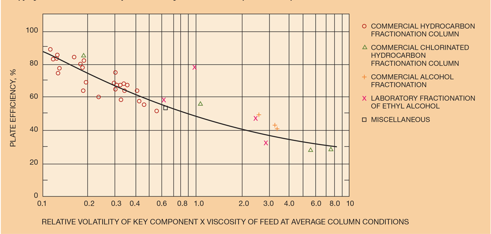
Rule three
Are the trays operating at their expected tray efficiency? If not, some hydraulic issue is implicated. The O’Connell plot (Figure 1)1,6 usually estimates distillation tray efficiency within plus or minus 25%. An updated version with a more fundamental basis has been proposed7 but the experience with it thus far has been limited.
For absorbers, there is an alternative plot by O’Connell.1,6
Rule four
Are the packings operating at their expected efficiency? If not, some hydraulic issue (in most cases, flooding, liquid or vapour maldistribution) is implicated. Packing efficiency is expressed as height equivalent to a theoretical plate (HETP). The HETP in metres, as a function of ap, the packing surface area per unit volume, m2/m3 for organic and hydrocarbon systems, surface tension < 25 dynes/cm, is:
HETP = 93 / ap metal random packings, 1 in or larger
HETP = 100 / ap + 0.1 Y-type or 3rd generation structured packings
HETP = 145 / ap + 0.1 X-type structured packings, ap < 300 m2/m3
Multiply the above values by 2 for water due to its higher surface tension (70 dynes/cm). For intermediate surface tensions, interpolate.
These rules of thumb are generally plus or minus 25% and assume good industrial-grade liquid and vapour distribution (not perfect like in test columns).
Rule five
Are the trays operating in the spray regime? If so, special considerations apply. When the weir loads exceed 2–3 gpm/in of outlet weir length, trays usually operate in the mixed froth or bubbly (emulsion) regimes. In these regimes, liquid is the continuous phase and vapour is dispersed as bubbles in the liquid. These regimes tend to obey the classic tray hydraulics as described in most distillation texts.1,2,3,4
Spray regime occurs at weir loads of less than 2–3 gpm/in of outlet weir length.1,4,8 Here, the vapour phase becomes continuous with liquid dispersed as drops in the vapour space. The vapour can then find its way into the downcomer and unseal it. In conventional trays operating in the spray regime, downcomers may lose their liquid seals. At low liquid rates, it is also important to keep the liquid on the tray and prevent drying by avoiding weeping and by using devices like picket-fence weirs,1,5 and to avoid level control on the liquid supply to the trays.
A downcomer is prone to losing its liquid seal in the spray regime when the liquid head loss at the downcomer exit is < 0.4 inches of liquid, and especially below 0.2 inches of liquid. The downcomer exit head loss can be estimated from

uexit is in ft/s. The area used in the calculation is based on the most restrictive area for liquid flow at the downcomer exit.
Rule six
Are the trays likely to experience vapour channelling? Vapour channelling reduces tray efficiency and causes premature floods. Channelling is likely to occur on trays when all four factors listed below come together:
- a high fractional hole area (hole or open slot area/active area) on the tray (> 11% with sieve trays, > 12% with fixed valve trays, > 13–14% with sharp orifice moving valve trays or any venturi (smooth orifice) moving valve trays)
- a ratio of liquid flow path length to tray spacing above 2
- a weir load exceeding 5–6 gpm/in of outlet weir
- pressure below 120 psia
Channelling is aggravated when one or more of these factors largely exceeds the limit above.
Rule seven
Recent Editions
Catch up on the latest news, views and jobs from The Chemical Engineer. Below are the four latest issues. View a wider selection of the archive from within the Magazine section of this site.


