Clean Hydrogen: Part 2
Producing large volumes of clean hydrogen, using methods other than from natural gas
ATOMIC and molecular hydrogen are most common beyond the Earth. Hydrogen is the primary constituent of the Sun, as well as most other stars, and it can be observed in vast quantities throughout the universe. Hydrogen is also the main component of the atmospheres of gas giant planets, Jupiter, Saturn, Uranus and Neptune. Because Earth’s atmosphere contains oxygen, any atomic hydrogen that might have been present has reacted to form water.
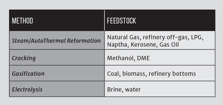
As a result, unlike natural gas, if a source of hydrogen is required, it has to be extracted from the compounds that it has formed. In the majority of cases this is water. This extraction process requires energy, and the application of technology to prevent the hydrogen from re-combining with oxygen to form water again. There are four principal methods to manufacture hydrogen, as shown in Table 1, dependent upon what feedstock is being used as the starting point.
Hydrogen as a by-product of other industrial processes
A small number of industrial processes produce hydrogen as a by-product of the extraction of other chemicals. An example of this is in the production of chlorine, which is achieved by the electrolysis of brine (salty water/sodium chloride solution), known as the chlor-alkali process. The production of chlorine also results in caustic soda (sodium hydroxide, NaOH) as a by-product. These two products, as well as chlorine itself, are highly reactive. Chlorine can also be produced by the electrolysis of a solution of potassium chloride, in which case the co-products are hydrogen and caustic potash (potassium hydroxide). There are three industrial methods for the extraction of chlorine by electrolysis of chloride solutions, all proceeding according to the overall process equation, note all release hydrogen:
2NaCl (or KCl) + 2H₂O → Cl₂ + H₂ + 2NaOH (or KOH)
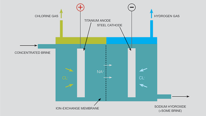
Production of chlorine is extremely energy intensive: energy consumption per unit weight of product is similar to that for iron and steel manufacture and greater than for the production of glass or cement. Since electricity is an indispensable resource for the production of chlorine, the energy consumption corresponding to the electrochemical reaction cannot be reduced. Energy savings arise primarily through applying more efficient technologies and reducing ancillary energy use, and process economics can be enhanced by marketing the by-products. For the hydrogen and the hydroxide to be marketable, they need to be of a high purity, and therefore the preferred production method is usually membrane cell electrolysis, as shown in Figure 1.
Hydrogen from the electrolysis of water
The principle of the cell shown in Figure 1 can be used with water instead of brine, in which case hydrogen emerges at the cathode and oxygen at the anode. In this context, the cell is known as an electrolyser, and single cells up to about 2 MWe are available commercially with efficiencies of around 80%. The levels of purity can be very high and the water pumped in at pressure, which means that the hydrogen is also at pressure. Electrolysers have a number of advantages over some other methods of hydrogen production, which include:
- individual cells can be clustered, making it a scalable technology;
- with no moving parts, maintenance is low;
- cells are agnostic with regards to the electricity source, and can use ‘spill power’ from wind generators or unsold ‘base load’ from nuclear power stations; and
- used in conjunction with wind or solar generation, they are “zero CO₂ emissions” at source (ignoring any CO₂ emitted in the water supply).
Hydrogen produced on refineries
Specifications for transportation fuels are continuously changing to accommodate environmental objectives. For example, petrol now contains less aromatics and olefins than they did ten years ago, and constraints have been imposed on light hydrocarbons and sulphur contents. New legislation for diesel requires deep desulfurisation down to 10–50 ppm sulfur. This is achieved by reacting the sulfur compounds with hydrogen to produce hydrogen sulfide (H₂S), which can be removed from the hydrocarbon stream by one of a number of processes. The requirement to reduce the sulfur may be achieved coincident with the removal of aromatic compounds, which are considered as carcinogenic. In general, these trends result in an increasing hydrogen content in the fuels (the H:C ratio is approaching 2). This has been achieved simultaneous with the crude slate becoming heavier, with higher contents of sulfur and metals in the crude. This has created a large requirement for more hydrotreating (HDS, HDN, HDM) and hydrocracking as a part of the refining processes. The hydrogen balance in a refinery is illustrated in Figure 2.
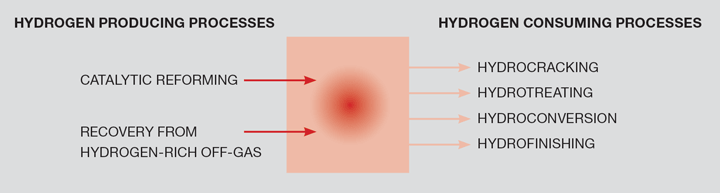
Traditionally, a major a part of the hydrogen consumption in refineries was covered by hydrogen produced as a by-product from other refinery processes, mainly catalytic reforming, described as ‘platforming’. A main reaction in catalytic reforming (not to be confused with catalytic steam reforming, which was described in Part 1 of this series) is the conversion of paraffins into aromatics and hydrogen. As specifications require that the aromatic content of fuels is further reduced, less hydrogen will become available from platforming.
Dependent on the slate and the product mix, some refineries will be ‘short’ on hydrogen and others will be ‘long’. Those refineries that are ‘hydrogen short’ have a number of options to make up the deficit, which include importing it from an adjacent SMR facility (as at the Lindsay refinery). Another option is to gasify the residual oils at the end of the process (‘refinery bottoms’), as described below.
Those refineries that are ‘hydrogen long’, if there are no export opportunities, may use it to fuel fired process heaters. These have the potential to realise more value from the hydrogen by exporting it to industrial users.
Gasification as a route to produce hydrogen
The principal reactions described for SMR in Part 1 of this series represent partial oxidation of the methane. The same reaction can be applied to almost any carbon-containing feedstock, including coal, refinery bottoms, domestic waste, industrial plastic waste and biomass. Instead of the partial oxidation reaction being promoted by a catalyst(s), gasification involves reacting the feedstock sub-stoichiometrically with oxygen (ie with insufficient oxygen available to allow the reaction to proceed to completion). Of these feedstocks, the focus for bulk production of hydrogen has been on coal and refinery bottoms.
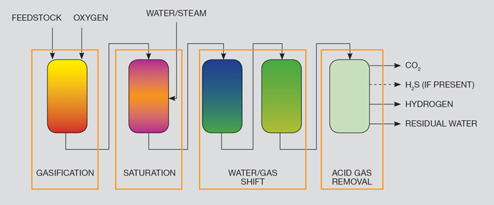
There are a number of different gasifier designs, but for hydrogen production a sub-set of these is favoured. For instance, gasification processes using air (instead of oxygen) tend to deliver a hydrogen/nitrogen mix at the end of the process, rather than pure hydrogen. A generic flowscheme to produce hydrogen using gasification is shown as Figure 3. The process is carried out under pressure, typically over 25 bar.
Plasma gasification is a variant of gasification which converts organic matter (such as sorted domestic waste) into syngas using a plasma torch powered by an electric arc. Anything else in the feedstock is left as a slag. Small plasma torches typically use an inert gas such as argon where larger torches require nitrogen. A high voltage passes between the two electrodes as an electric arc. Pressurised inert gas passes through the plasma created by the arc and is ionised. The temperature of the plasma can be anything from 2,200–13,500°C depending on the process, the temperature largely determining the structure and shape of the plasma. The feedstock beneath the plasma is vapourised at these temperatures, and molecular dissociation takes place: the complex molecules are split into simple molecules (such as CO or H₂), or even individual atoms. The syngas thus formed can be used as a source of hydrogen or methanated to produce ‘synthetic natural gas’.
It is relatively easy to link gasification with carbon capture and storage (CCS): where biomass is used as a feedstock, this can result in ‘negative CO emissions'.
Hydrogen from residual oil
A refinery has a high electricity demand, and burning the syngas in a gas turbine to offset the import of electricity is a possibility to manage changes in the hydrogen demand of the refinery. Examples of where this has been or will be employed are provided in Table 2.
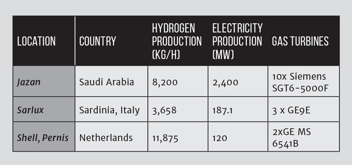
A feedstock of residual oil (“refinery bottoms”), asphaltines or bitumen is heated and pumped into a gasifier, as described above. The operating mode is usually that the process produces hydrogen for the refinery (eg for upgrading heavier elements of the slate), with electricity generation being used to utilise ‘spill hydrogen’ beneficially.
Hydrogen from micro-organisms
Hydrogen can be produced by a number of different micro-organisms: which ones and the associated science is beyond the scope of this series. Perhaps the most successful example of this has been attributed to researchers from Germany, who have an experimental facility in the Sahara producing hydrogen using a bacterium called Thiorhodaceae. This is carried out in a heliomite, a cone-shaped wooden construction with a transparent plastic pipe for the movement of the bacteria (Hydrogen Today, Vol 7, No 1).
Results show that the rate of hydrogen production almost doubles when the heliomite receives sunlight from a side (as opposed to the top) as Thiorhodaceae favours the long-wave light reflected by the Sahara sand. The researchers combined bacteria and plant photosynthesis to provide nutrients for the bacteria. In this experiment, green algae and Thiorhodaceae are positioned adjacent to each other. The green algae react with the bacterial carbon dioxide and water to form oxygen and carbohydrates. The oxygen escapes and the carbohydrates feed the Thiorhodaceae solution, which produce a mixture of CO₂ and hydrogen. Each heliomite can produce up to 0.285 Nm³/h of hydrogen.
Clearly this technology has a way to go before microbial hydrogen can make a significant impact on the current carbon-based economy, but it has the potential to make a contribution.
Dark fermentation
Hydrogen production by dark fermentation could be a very promising concept. Dark fermentation is described as the fermentative conversion of organic substrate to produce bio-hydrogen. It is a complex process manifested by diverse groups of bacteria, involving a series of biochemical reactions using three steps, similar to anaerobic conversion. Dark fermentation differs from photo-fermentation in that it proceeds without the presence of light.
However, this process has only been studied on the laboratory scale, and there is limited experience at the pilot scale. There remain a number of challenges with hydrogen purity, process stability and low conversion yields, all of which seem not to improve with increasing scale.
Thermochemical hydrogen production
Thermochemical water splitting uses high temperatures and chemical reactions to produce hydrogen and oxygen directly from water. Possible heat sources include concentrated solar power or, potentially, nuclear power. This is thought to be a long-term technology pathway, with potentially low or no direct greenhouse gas emissions. Figure 4 shows the principle using solar rays as the heat source.
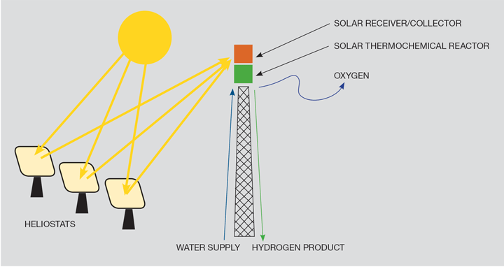
Thermochemical water splitting processes use high-temperature heat (500°–2,000°C) to drive a series of chemical reactions that “split water” into its component parts of hydrogen and oxygen. The chemicals used in the process are reused within each cycle, creating a closed loop that only consumes the water and produces hydrogen and oxygen gasses.
Hydrogen production by nuclear fission
Purely nuclear based production of hydrogen was observed in the 1940s in experimental nuclear reactors based on the Aqueous Homogeneous Reactor (AHR) concept, where the nuclear fuel is dissolved in the water coolant and circulates between the reactor core and a heat sink. These reactors were originally given the name ‘water boiler’ due to the observed bubbling of the liquid fuel. The bubbles are hydrogen and oxygen gas formed by radiolytic dissociation of the water from the ionising radiation of energetic neutrons and fission fragments. Radiolysis is actually considered a serious problem for water reactors, since it can lead — and has led — to explosions in the reactor system.
Due to the low energy efficiency of hydrogen production, this method was not considered promising as a commercial dedicated hydrogen production method.1
Hydrogen as a low carbon energy vector
Hydrogen production by any method only makes sense if it does not also emit CO₂. In many instances, for example, gasification of refinery residues, the process lends itself to carbon capture and storage (CCS). CCS is necessary to make the technology acceptable environmentally. Were biomass to be used as a feedstock, then a case can be made for the hydrogen to have ‘negative emissions’. Avoiding payments to emit CO₂ will assist Industry in offsetting some of the additional costs associated with fuel switching from natural gas to hydrogen (in whole or in part).
It is outside of the scope of this article to describe how CCS can complement hydrogen production, but an obvious synergy is that CCS infrastructure developed to support hydrogen as a low carbon energy vector could, under appropriate commercial and other conditions, then be available for use by other industries such as fertiliser and cement production, and steel making.
Reference
1. © International Atomic Energy Agency, "Hydrogen Production Using Nuclear Energy", IAEA Nuclear Energy Series No. NP-T-4.2, IAEA, Vienna (2012). Used with permission.
This is the fourth article in a series discussing the challenges and opportunities of the hydrogen economy, developed in partnership with IChemE's Clean Energy Special Interest Group. For more entries visit the series hub.
Recent Editions
Catch up on the latest news, views and jobs from The Chemical Engineer. Below are the four latest issues. View a wider selection of the archive from within the Magazine section of this site.


