Clean Hydrogen. Part 1: Hydrogen from Natural Gas Through Cost Effective CO2 Capture
TODAY, hydrogen is predominantly made by steam reforming of natural gas, which produces carbon dioxide as a byproduct. The reforming reaction for methane is:

In addition, the water gas shift reaction can be favoured by process conditions to generate further hydrogen:

The Hydrogen Council initiative quotes the global production of hydrogen to be 8 EJ/y (71,600 kNm³/h) with a majority of users in refineries ammonia and methanol production. Growth is forecast in these markets and there is a growing body of evidence that to reduce carbon dioxide emissions to acceptable levels, deeper cuts across all sectors will be required. A low carbon gas solution for hydrogen production will be important to achieve the aims of the Paris Protocol and impact on climate change.
Compared to conventional steam methane reforming (SMR), the Low Carbon Hydrogen (LCH) flowsheet developed by Johnson Matthey offers a better solution for hydrogen generation with carbon capture by:
- recovering high-grade heat at the maximum exergy;
- using high reformer temperatures to minimise methane in the syngas and hence carbon dioxide emissions; and
- increasing energy efficiency and CAPEX benefits by recovering all the carbon dioxide at process pressure; and
- minimising the amount of difficult-to-capture CO2 in combustion products.
Steam methane reforming
Critical to the process is the SMR which generates the majority of the world’s hydrogen1 as shown in the flowsheet in Figure 1. The SMR is a large refractory-lined box containing hundreds of pressurised tubes to convert hydrocarbon as per the reaction above.
To achieve long catalyst lives, the first stage in the process purifies the natural gas by a hydrodesulfurisation step in which the organo-sulfur compounds are reacted over a catalyst with recycled hydrogen to form hydrogen sulfide followed by absorption of that hydrogen sulfide in a zinc oxide bed through its conversion to zinc sulfide.
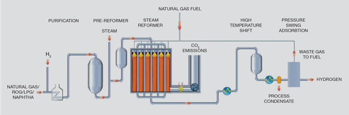
In an SMR, hydrocarbons present in the feed natural gas are reacted with steam at pressures of between 1m–4m Pa in the presence of a nickel catalyst in tubes, which are generally 12–14 m in length with a 125 mm inside diameter.
The reaction produces a gas mixture comprising hydrogen, carbon monoxide and carbon dioxide, which is often termed “syngas”. The steam reforming reaction is endothermic, so heat is added to the process by burning additional natural gas and waste gas streams to heat the catalyst-containing tubes. Typically, the reformer exit temperatures are between 700–930°C depending on the flowsheet and final product.
The syngas from the steam reformer is further processed over a third and, in some cases, a fourth catalyst stage when the water gas shift reaction takes place as detailed above to maximise hydrogen production. This reaction is exothermic and cooling the gas allows heat recovery back into the process which generally involves steam generation and boiler feed water pre-heating.
SMR flowsheets have been optimised over a number of years and have become the technology of choice to produce hydrogen, with production capacity ranging from MWs to GWs (1–330 kNm³/h). The designs are now deemed to be a mature technology that provides high purity hydrogen on a reliable basis required for downstream users. However, there are very few hydrogen plants that capture the carbon dioxide as there is no economic or legislative incentive to do so.
Therefore, if hydrogen is to play a role in reducing the impact of climate change2, then it will need to be produced with concomitantly low carbon dioxide emissions, which, when using natural gas as a feedstock implies coupling it with carbon capture and storage (CCS). The combustion process in an SMR produces carbon dioxide at low concentration and atmospheric pressure and hence inevitably leads to high capital cost estimates (CAPEX) solutions for CCS. These include post-combustion capture of the carbon dioxide or using process-produced hydrogen as the fuel in the reformer. Both of these introduce significant efficiency losses.
Accordingly, to produce low carbon hydrogen cost effectively, the products are ideally both high purity hydrogen and also now high pressure and high purity carbon dioxide for CCS. Additionally, consumers of this hydrogen would not want this with an unaffordable cost penalty.
Introducing low carbon hydrogen (LCH) technology
The LCH flowsheet recovers heat at maximum exergy (ie the highest possible quality) which offers efficiency benefits by coupling a gas heated reformer (GHR) with an autothermal reformer (ATR). The main difference between the LCH and SMR flowsheets is that the energy to drive the reaction is provided by introducing oxygen to the ATR as opposed to burning natural gas in the SMR. At the scales envisaged, this oxygen would come from an air separation unit. ATRs are already used in the production of syngas and are part of most modern schemes for production of methanol and liquid fuels from Fischer- Tropsch processes. These plants are very large and demonstrate that the technology is capable of producing hydrogen at large scale and therefore the scale-up risk is minimised.
At a basic level, a flowsheet showing hydrogen production using LCH technology is shown in Figure 2.
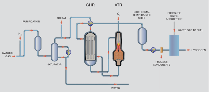
Purified natural gas is pre-heated and reformed in the GHR before entering the ATR reactor. In the first reaction step in the GHR, 30% of the total hydrocarbon is reformed by reaction with steam to form syngas. In the second stage, the ATR, oxygen is added and combusts some of the partially-reformed gas to raise the process gas temperature to around 1,500°C. The resultant gas then passes through a bed of steam reforming catalyst inside the same reactor for further reforming. Since the reaction is limited by equilibrium, operation at high temperature and steam flows minimises the methane content of the product gas which in turn minimises overall carbon dioxide emissions. The hot gas exiting the ATR passes back to the GHR providing the heat necessary to drive the reforming reaction in the GHR tube- side.
For the LCH flowsheet, all of the carbon dioxide is within the product stream and therefore is at high pressure and relatively high purity and can be easily removed using standard industry removal technologies. This has implications in terms of the overall CAPEX of the flowsheet because the size of the carbon dioxide removal system is significantly reduced.
The advantages of a LCH flowsheet are that:
- heat is recycled at a higher quality than in an SMR flowsheet which uses medium pressure steam as a heat transfer medium; and
- the reforming reaction is conducted at a higher temperature, which means more methane is converted to hydrogen
Comparison of the technologies
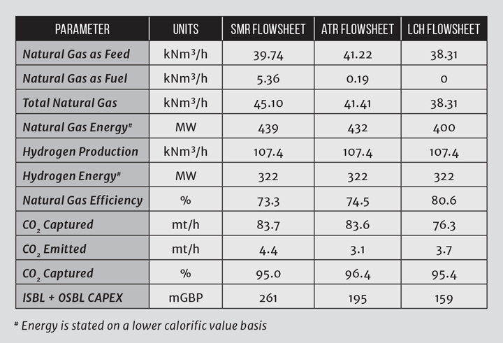
Whilst steam reforming using an SMR requires a large energy input from combustion of natural gas, energy integration means the flowsheet is relatively efficient. In an SMR, the waste heat generated primarily as steam is exported, whilst for an SMR with CCS, the steam is used to provide heat for carbon dioxide recovery and energy for carbon dioxide compression. In the LCH flowsheet, the waste heat is instead recycled to supplement the necessary reaction heat through the GHR, meaning natural gas fuel is not needed, resulting in reduced atmospheric emissions as illustrated in Table 1.
So, the benefits of the LCH flowsheet are:
- it recycles exergy at the high possible level;
- it uses high reformer temperatures to minimise methane in the syngas and hence CO2 emissions; and
- all of the CO2 is recovered at process pressure, which offers energy efficiency and CAPEX.
A further advantage of using the LCH technology is that compression energy required for the air separation unit and carbon dioxide compression need not be by steam raising. The LCH flowsheet can power compressors using electrical grid energy sourced from renewable energy sources. The LCH technology therefore can integrate renewable energy and provide a flowsheet with dramatically reduced greenhouse gas emissions, lower capital cost and lower natural gas consumption.
GHRs have run continuously on a commercial basis for over 100 cumulative years proving the concepts on a long term with best in class reliability. The technology has been scaled and in 2016 to facilitate a 5,000 mtpd methanol project in the US. In 2016, JM’s technological breakthrough was awarded the top prize at the IChemE Global Awards (Outstanding Achievement in Chemical and Process Engineering).
References
1. Appl, M, Modern Production Technologies, CRU Publishing, 1997
2. https://unfccc.int/process-and-meetings/the-paris-agreement/the-paris-agreement
This is the second article in a series discussing the challenges and opportunities of the hydrogen economy, developed in partnership with IChemE's Clean Energy Special Interest Group. For more entries visit the series hub.
Recent Editions
Catch up on the latest news, views and jobs from The Chemical Engineer. Below are the four latest issues. View a wider selection of the archive from within the Magazine section of this site.