The Heat is On
Keith Plumb explains the importance of design of pressure relief systems for stirred tank vessels
THERE are a number of scenarios where heat input into stirred process vessels could lead to overheating the vessel contents, which in turn could lead to boiling of these contents and over-pressurisation of the vessel.
The purpose of this article is not to provide methods to allow a detailed pressure relief calculation to be carried out, because this is not possible in a single article. The reference list includes documents that are over 100 pages long, illustrating the scale of the calculation requirements.
The intention of this article is to provide an overview of the factors that need to be taken into account and to allow the reader to have better understanding of their particular problem so that they can set off in the correct direction to carry out the required design.
Relief scenarios
The design of a pressure relief system is only as good as the relief scenarios that are developed. Reference 1 is one source of information for pressure relief scenarios, but is focussed mainly at the oil and gas sector and may not be appropriate for other process sectors.
Since the development of the relief scenarios is so important, sufficient time should be dedicated to this activity. My recommendation would be to carry out a brainstorming session, with members of the design, commissioning, operating and maintenance staff in attendance to ensure that all credible relief scenarios are identified.
Heat input scenarios
There are at least four credible scenarios for heat input into stirred vessels that could lead to overheating the vessel contents which in turn could lead to boiling of these contents and over-pressurisation of the vessel.
These scenarios are:
- heat input from a jacket or coil;
- heat input from a pool fire;
- heat input from a jet fire; and
- a runaway reaction.
Since scenario 4 is not strictly heat transfer across the vessel wall but heat generated within the vessel contents, this scenario is not given further consideration in this article.
To be able to size the relief device it is necessary to know what is the potential heat input into the vessel. Using the latent heat of vaporisation of the contents, it is then possible to calculate the flow of vapour that the relief device needs to pass.
Examine the scenarios in detail
In my experience it is often assumed that the heating by a pool fire or jet fire will lead to the highest heat input and further consideration is not required. However, having carried the detailed design on many stirred vessels, it is clear that this is not always the case and detailed examination of these heat transfer scenarios is important to achieve the required basis of safety.
Scenario 1: Jacket or coil
Heat input from a jacket or coil can be modelled using the classic heat transfer equation:

Where:
Q = Heat transferred (W); U = Overall heat transfer coefficient (W/m2K); A = Wetted surface area (m2); Tj = Temperature of the contents of jacket or coil (K); Tb = Boiling temperature of vessel contents and the relief pressure (K).
This simple equation tells us that physical properties of the jacket or coil contents will be important firstly to determine U but also the boiling temperature of the vessel contents.
The temperature of the jacket will depend on the details of the relief scenario. So, if for example, the scenario is that a steam reducing valve has “failed open” then it is credible that the worst-case jacket temperature will rise to the saturation temperature of steam at the pressure upstream of the failed pressure reducing valve.
This simple equation makes it clear that the heat input could be much higher for a low boiling than a high boiling liquid.
Scenario 2: Pool fire
To get a better understanding of the heat input from a pool fire, consideration of the likely type of pool fire is the first step. The current design methods for pool fires are based on the work of Cummings, which is detailed in Reference 3 and this was based on the definition of three types of fire:
- Catastrophic fire: “The catastrophic fire is one in which the vessel is practically completely surrounded by fire. An example would be a vessel located inside a building or enclosure where the absence of air currents permits the flame to surround the vessel to considerable depth.”
- Uncontrolled fire: “An uncontrolled fire is one in which the only favourable factor limiting the heat input to the vessel is the wind, which tends to carry the flame off its target. All other factors are unfavourable. Nothing has been done in advance to reduce the fuel supply and no attempt is made to extinguish the fire.”
- Controlled fire: “Fires in which the exterior environment is such as to withdraw the fuel away from the vessel and where prompt effective means to extinguish the flame are employed are considered controlled.”
BASIC HEAT TRANSFER EQUATION
The basic heat transfer equation proposed by Cummings was:

Where Q = Heat transferred (W); A = Wetted surface area (m2); Qf = Fuel factor (W); E = Exposure factor (dimensionless); F1 = Exterior environment factor (dimensionless); F2 = Adjacent environment factor (dimensionless).
For controlled and uncontrolled fires numerous sources use E = 1/A0.18. This exposure factor results in the following equation:

In the latest version of API 521 (listed as Reference 1) this has been further simplified to:

Where prompt firefighting efforts and drainage of flammable materials away from the vessel are available, API 521 gives Qf = 43,200 W, if this is not the case then Qf = 70,900. It is important to remember that the fuel factor is based on fires for kerosene, gasoline and butane and may not be appropriate for the fuel that you are considering.
For catastrophic fires E = 1.0 and the basic equation becomes

Table 5 of Reference 1 gives the values for F which are based on amount of insulation on a vessel. For a bare vessel, F = 1.0 and for low levels of insulation F = 0.3. The factor decreases as the level of insulation increases, with F =0.026 being the lowest value. It is important to note the insulation must resist being dislodged by fire hose streams.
Scenario 3: Jet fire
Jet fires can provide a higher level of heating. Table A.4 in Reference 1 gives values of jet fires of 30–120 kW/m2 compared with 25–75 kW/m2 for pool fires (Reference 1, Table A.2). However, it is important to consider that a jet fire is unlikely to heat the full wetted surface area of the vessel.
Example
This example is based on information provide in Reference 2.
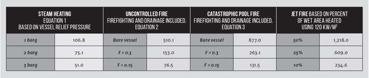
Consider a 7 m3 stirred vessel (working volume) with a 45º pitched blade turbine with a diameter of 1/3 vessel diameter, rotating at 91 rpm plus a steam heated half-coil jacket. Reference 2 gives the heat transfer area as 15.9 m2 and a wetted surface area of 20.3 m2. The vessel contains water.
With steam in the half-coils and water in the vessel, Reference 2 indicates that the overall heat transfer coefficient would be 150 W/m2K. Assuming that the steam in the half-coils is 6 barg and based on the details and information above for heating by fire, Table 1 can be generated.
The information above is illustrative and must not be used for design. It is important that detailed calculations are carried out for each real-life situation.
The heat input from the heating coil of a stirred vessel is in the same order of magnitude as the potential heat input from a pool or jet fire
However, this example shows a number of important points. For steam heating, the temperature of the boiling liquid is important. In this example the vessel contains water but if it contained a low boiling solvent the heat transfer rate could be 2 to 3 times higher.
The results for uncontrolled fires show the importance of insulation. To take credit for insulation it is important to understand what would happen to the insulation in a fire. A further consideration is the impact of a heating coil. There may be a scenario where a fire causes the steam heating to continue to heat the vessel and there could be heat input from both sources.
Catastrophic fires are relevant to vessels inside buildings. Since it is very common for stirred vessels to be located inside buildings, consideration needs to be given to whether a catastrophic fire would occur, and that the higher heating levels should be used for pressure relief design.
The jet fire gives the highest heat input but it is important to remember that I have used the highest value given in Reference 1 here and it is not clear what the impact of insulation would be on the heat input. If a jet fire is a credible scenario then detailed examination of this scenario is required.
Conclusion
The heat input from the heating coil of a stirred vessel is in the same order of magnitude as the potential heat input from a pool or jet fire. This illustrates the importance of examining all credible scenarios in detail when designing the pressure relief system for a stirred process vessel.
References
1. Pressure-relieving and Depressuring Systems API Standard 521 Sixth Edition, January 2014
2. Paul, EL, Atiemo-Obeng, VA, Kresta, SM, (2004). Handbook of Industrial Mixing - Science and Practice – 14 Heat Transfer.
3. Cummings, LWT, “Required Relieving Capacity of Vessels due to Exterior Fire Exposure”, (Available as appendix A of Reference 4).
4. Heller, FJ, “Safety Relief Valve Sizing: API Versus CGA Requirements Plus a New Concept for Tank Cars”. Safety Device Use and Application.
Recent Editions
Catch up on the latest news, views and jobs from The Chemical Engineer. Below are the four latest issues. View a wider selection of the archive from within the Magazine section of this site.


