The Challenges of Developing a Fusion Power Plant: and How Chemical Engineers are Helping Make STEP a Reality
In part two of our series on fusion energy, Jack Acres highlights the core challenges of developing a prototype power plant and how chemical engineering principles are being used to solve them
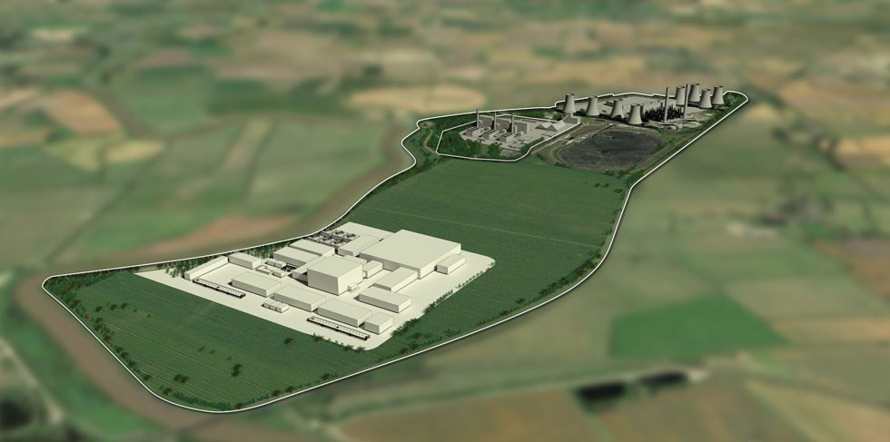
THE SITE of a coal-fired power station in North Nottinghamshire is poised to take centre stage on the journey to commercialising fusion energy as a safe, sustainable, low-carbon energy source often described as the “holy grail” of energy.
West Burton A site will be home to the STEP (Spherical Tokamak for Energy Production) prototype fusion energy plant, which aims to generate electricity for the National Grid in the 2040s, paving the way for the development of future commercial plants.
Chemical engineers have been integral to the concept design of STEP. Core chemical engineering principles have been used throughout, specifically in the fuel cycle, thermal power transfer, and power generation areas of the design. Process models, heat and mass balances and unit specific models have been calculated. Process flow diagrams, process descriptions, and process technology selection reports have been drafted.
In 2024, the programme will move forward to the next tranche, away from concept design and into a more detailed engineering phase.
However, there are still distinct technological challenges which must be addressed to ensure the development of a sustainable prototype fusion energy plant.
With elements of heat transfer, fluid flow, and separations processes dominating the STEP design, chemical engineers will continue to be integral to the success of the project.
Here, we look at some of the challenges that still need overcoming.
What is Fusion Energy?
Fusion can be thought of as the opposite of fission – combining lighter atoms rather than splitting heavier ones.
When a mix of two types of hydrogen (deuterium and tritium) are heated to form a plasma at extreme temperatures (10 times hotter than the core of the sun) they fuse together to create helium and release huge amounts of energy.
There is more than one approach to achieving fusion. Examples include magnetic confinement and inertial confinement. At UKAEA, they hold the plasma using strong magnets in a ring-shaped machine called a tokamak.
How will power be generated?
At its core, the STEP prototype fusion plant will generate power by using a heat source to run a thermodynamic cycle which provides power to the grid. However, there are unique aspects and distinct challenges linked to power generation from fusion energy. To evaluate these challenges, one must first understand:
- the different tokamak elements which produce thermal power
- the holistic power plant enabling fusion, which also enables conversion and export of electrical power
The goal of STEP is to generate net electrical power; this is achieved by converting thermal power to electrical power.
Heat will be generated by the collision of the atomic particles which fuse and create heat from mass (e=mc2). STEP will enable the fusion of deuterium and tritium particles, ensuring a maximum yield of power with hydrogen isotopes.
This fusion reaction releases large amounts of energy (known as fusion power or Pfus) as both neutronic heating and alpha particle heating. In turn, this energy is converted into heat within the tokamak (across various “in-vessel components”) and then extracted to generate electrical power.
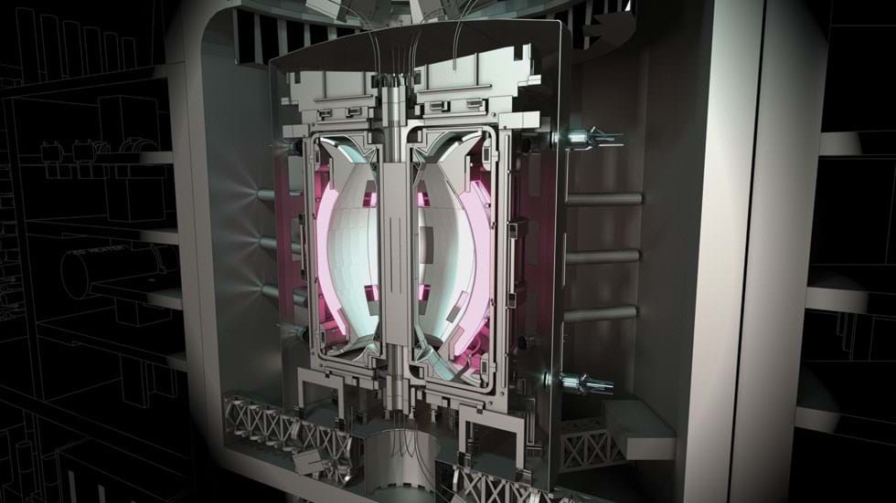
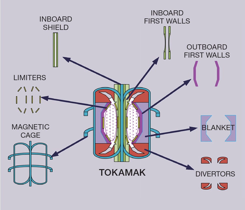
Inside STEP
The spherical tokamak is made up of several in-vessel components, including:
- Magnets: Must confine and contain reactive plasma heated up to 150 million degrees Celsius
- First walls: Must resist radiative heat loads emitted from the plasma
- Blanket: Must convert neutron to heat and tritium – our fuel
- Exhaust divertors: Must process exhaust plasma gases. This sees the highest heat load in the machine up to 20 MW/m2 – to put this into context, the space shuttle endured only ≈4 MW/m2 on re-entry!
All components require cooling and heat extraction to some degree, due to the significant heat loads imposed by radiative heating and neutronic flux within the tokamak. It stands to reason that to maximise power production, as much of the heat as possible from these components should be captured and integrated into a thermodynamic power cycle, as far as reasonably practicable.
One instance where this is not practicable is the magnets. These are cryogenically cooled to sustain superconducting abilities and therefore heat generated here cannot be integrated into a power generating cycle. Instead, refrigeration technology is required to keep the magnets cool.
The intense heat loads of most in-vessel components are a significant heat transfer challenge which many chemical engineers will be familiar with.
The in-vessel conditions as well as the components’ design, in turn, will have a direct influence on the coolants chosen, as well as their operating parameters. The choice of coolants in the tokamak remains a pivotal design decision, usually resulting from a series of targeted design trades. Significant optioneering is required at the concept design stage to understand compatibilities between coolants as well as assessing overall performance of the prototype plant design.
Inside STEP prototype plant
STEP will be made up of different systems to ensure the ability to effectively extract and convert thermal energy into electrical power. The systems will also ensure the operability and self-fuelling ability of the fusion reaction – both are critical elements to ensure a truly sustainable energy solution.
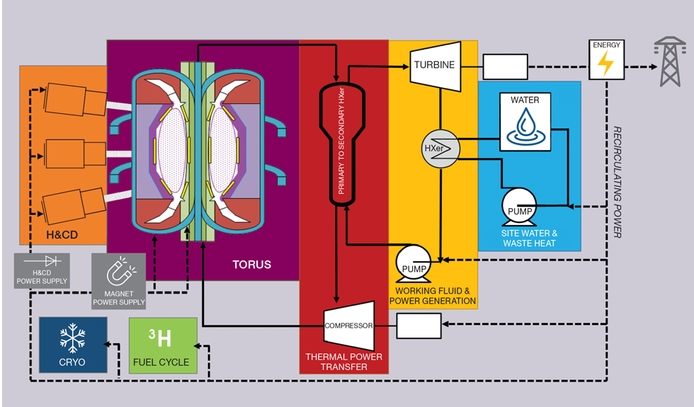
Heating and Current Drive (or H&CD) System
The heating and current drive system is responsible for heating the plasma. To mimic the conditions of the sun and enable fusion, the temperatures of the plasma must reach up to 150 million degrees Celsius. This is in fact hotter than the sun to compensate for the lack of pressure achieved in the sun’s core but not attainable in a fusion machine. In a tokamak, fusion is contained using magnetic fields. Strong magnets are required to confine the plasma, but the plasma itself must also have a current to enable this and magnetic stability must be achieved. A heating and current drive (H&CD) is required to sustain the large temperatures and ensure adequate control/stability of the plasma. This can be achieved with neutral beam injections or radio frequency devices.
The heating and current drive system sees significant power loads and the inefficiencies of these loads result in a large amount of waste heat. Meanwhile, the cooling water requirements lead to very large cooling water flow rates and systems that require careful design which must also take into account the purity of water needed.
Thermal Power Transfer System
The Thermal Power Transfer System encompasses all systems used to extract useful heat from the tokamak’s in-vessel components. Useful heat is defined as heat used for power generation and therefore integrated into a wider thermodynamic power cycle. The temperature associated to the heat extracted will dictate whether it can be integrated into a thermodynamic cycle.
The thermal power transfer system consists of a series of cooling loops which are used to cool in-vessel components, while simultaneously extracting heat for a thermodynamic cycle. These cooling loops will include a circulating device (compressor/pump) and a heat exchanger to ultimately transfer heat into a working fluid. Coolants used in tokamaks are gases and/or liquids, which can range from simple water to more challenging liquid metal or molten salt coolants.
The cooling loops must be carefully designed to ensure the interface with individual in-vessel components is appropriately managed within the spatial constraints near the tokamak itself. They must guarantee return conditions, including temperature, pressure, and purity. Achieving this within the allowable space and layout constraints near the tokamak, while still operating in an optimised manner for power consumption, remains a challenge.
Guaranteeing return conditions is even more difficult when considering the rapid transience within the tokamak. Typical process control principles have been, and will continue to be, used to demonstrate the ability to handle plasma transience.
The tokamak operates within a unique neutron flux which, in turn, can affect the impurities formed within coolants. Purification steps for coolant fluids will therefore need further development over the next tranche of the project.
Working Fluid and Power Generation System
The working fluid and power generation system is effectively a thermodynamic power cycle (eg a steam Rankine cycle). The purpose of the working fluid and power generation system is to convert thermal power from the thermal power transfer system into electrical power. This is achieved by transferring heat in the “primary heat exchangers” from the primary coolants of the thermal power transfer system, and into the working fluid. In turn, the working fluid converts the thermal energy gained into electrical power within a prime mover (eg a turbine).
As with any thermodynamic/Carnot cycle, there is a heat rejection step to the environment required after the turbine, before the working fluid is pressurised again, using a pump.
The thermodynamic cycle of the STEP prototype fusion plant must integrate heat from multiple “primary heat exchangers” which are linked to individual in-vessel components of the tokamak, typically operating at different conditions. This represents a significant heat integration challenge.
Every megawatt of heat that can be integrated to generate additional kilowatts of electrical power is hugely significant, ensuring the ability to export net power to the grid in the first place. The heat integration of the thermodynamic cycle must therefore be optimised for a maximum power generation (within set design constraints).
Chemical engineers have used a number of tools, including process modelling, to optimise for power generation through wider heat integration into the design. This has enabled confidence in STEP’s ability to generate power.
Additional work is taking place to continue to explore heat integration in the next stages of design. This will help identify future opportunities for heat integration into the thermodynamic cycle, while also continuously addressing the feasibility and viability of the process design.
Chemical engineers have used a number of tools, including process modelling, to optimise for power generation through wider heat integration into the design. This has enabled confidence in STEP’s ability to generate power
Site Water and Waste Heat System
This cools all of STEP’s plant systems and reject waste heat by using cooling water systems.
While it is true that this system will broadly integrate major plant items with a high technology maturity, it should not be underestimated.
One unique aspect of this system is the level of complexity. There will be numerous users of the cooling water on site, such as the cryoplant and the heating and current drive systems, which will need specific levels of water purity and may have individual temperature constraints.
There will be other users closer to the tokamak such as diagnostic systems. The water coolant used here may require varying levels of treatment due to the exposure to a given neutron flux. The complexity of this system calls for holistic process integration within set design constraints and performance criteria with the aim of reducing electrical loads incurred in the wider plant.
This is a challenge which chemical engineers have been assessing. As the detailed aspects of the design mature, it is expected that many more users of cooling water will be identified, creating further complications to the process design, purification elements, and control systems.
Cryogenics
The cryogenics system transfers cryogens to the various users on site. Most fusion plant designs reliant on magnetically confined fusion will utilise superconducting magnets. These require low temperatures (4–20 °K) to function as intended, which can be challenging as they will see resistive and neutronic heat loads – even after neutron shielding. These heat loads must be managed with a significant cryogenic helium supply infrastructure. The cryogenic system is also responsible for generating and supplying cryogens to other areas of the plant, such as the fuelling system which relies on forming solid hydrogen pellets.
Electrical Infrastructure
The electrical infrastructure is used to manage and distribute the power generated from the working fluid and power generation system. The electrical infrastructure must transform and convert the electrical power as appropriate for the very demanding parasitic electrical loads across the plant (parasitic load = electrical power consumer on plant). Notoriously, significant power exchange is required throughout. The energy balance is managed such that enough power can be exported to the grid, making STEP a true “generating” plant, following a simple equation:
Net power export to the grid = Electrical power generated - Internal parasitic loads
Chemical engineers have been working with both electrical and cryogenics engineers to ensure an integrated approach to the STEP prototype fusion plant design and subsequent performance evaluation. In turn, this has ensured an ability to understand how STEP will perform, and how it will generate a net power export to the grid.
Using heat and material balances for a holistic plant design, we have been able to analyse the amount of power that will be generated by the prime mover. The team has also evaluated all significant process plant electrical loads (eg pumps, compressors, and cooling systems). The evaluation of these in addition to the other internal parasitic loads calculated by the wider inter-disciplinary team, has informed the ability to generate net power to the grid.
Fusion Fuel Cycle
Fusion fuels tritium and deuterium are both hydrogen isotopes. Deuterium is naturally abundant, but tritium must be bred to ensure the fusion plants are self-sufficient.
It is bred by purposefully integrating lithium into the in-vessel components (the blanket). Throughout the fusion reaction, neutrons are produced. In turn, these neutrons collide and react with the lithium which breeds tritium. Tritium formed must be extracted from these in-vessel components. Only a portion of fuel is consumed in the tokamak, with the remaining fuel recovered from the exhaust.
The fusion fuel cycle will manage tritium across the STEP prototype plant and will ensure fuelling to the tokamak as well as tritium recovery. This is further explained in the first article in this series (TCE, 988).
Chemical engineers solving fusion challenges: Jack Acres

After graduating with a chemical engineering degree from the University of Manchester, Jack joined UKAEA in his current role in 2020 following a career in oil and gas, and speciality chemicals.
Working within the STEP project team since joining UKAEA, Jack’s focus has been on developing power generation elements of fusion. This has involved understanding how the STEP prototype plant could generate power, converting thermal power from a novel tokamak into sufficient electrical energy which can be supplied to the grid.
Jack continues to lead a multi-disciplinary team of engineers in the development of a concept design solution which will demonstrate net power to the grid utilising a fusion power source – something which has never been done before.
Chemical engineers solving fusion challenges: Daniel Blackburn

After graduating with a chemical engineering degree from Aston University, Dan joined the UKAEA graduate scheme in 2021.
Working within the power infrastructure team on STEP, he has carried out technology assessments, feasibility studies, and calculations in different areas of the power cycle and coolant loops design. He is also responsible for the design of the cooling water system which will dissipate the waste heat from the power cycle and other parasitic loads. Additionally, Dan works in the STEP prototyping and testing team on the design of a rig that will be used to measure hydrogen permeation at high temperatures and pressures.
Energy revolutionaries
The STEP prototype fusion energy plant will be one of the first demonstrations of a novel technology that can truly make an impact in the fight against climate change and energy security, forever changing the energy landscape.
Undoubtedly, chemical engineers have and will continue to add value to the STEP project. This will be achieved by leveraging their unique skill sets, ensuring an integrated approach to the design delivered, while also developing targeted technologies and design for the success of the programme.
The STEP programme aims to pave the way for the commercialisation of fusion and the potential development of a fleet of future plants around the world, ensuring the UK remains at the forefront of a new technology and emerging industry.
The road to boundless energy is not an easy one, or it would have been done already. The integrated approach of STEP’s design continues to unearth challenges, but as we address these one by one, we get a step closer to achieving a future reality of truly sustainable and reliable energy.
As chemical engineers we have a clear role to play in the development of fusion technology. As a collective we have the responsibility to future generations in developing fusion as part of the ultimate energy solution.
Recent Editions
Catch up on the latest news, views and jobs from The Chemical Engineer. Below are the four latest issues. View a wider selection of the archive from within the Magazine section of this site.


