Taking a Look Back at Control: Part 1
Martin Pitt considers the history of process control in a two-part series, kicking off with mechanical and pneumatic controls
MY FIRST experience of control systems was on a summer placement before my last year in school. Under guidance I built an electronic system for controlled (and very slow) cooling of a crystalliser for Kodak. Transistors were available, but at that time they were not considered to have sufficient long-term stability for the process, so a thermionic valve was used instead.
I have also dismantled a still which was used to test process control by an IBM computer in early trials of the technology, and seen analog computers, as well as pneumatic controls and hard-wired relay logic. I was fortunate to work for many years with industrial experts on an industrial short course on control, and produced a book based on it, Instrumentation and Automation in Process Control (Pitt & Preece, eds, 1990).
However, process control has a long history before computers and electronics. Let’s see what was done even before I was born.
The one-legged stool
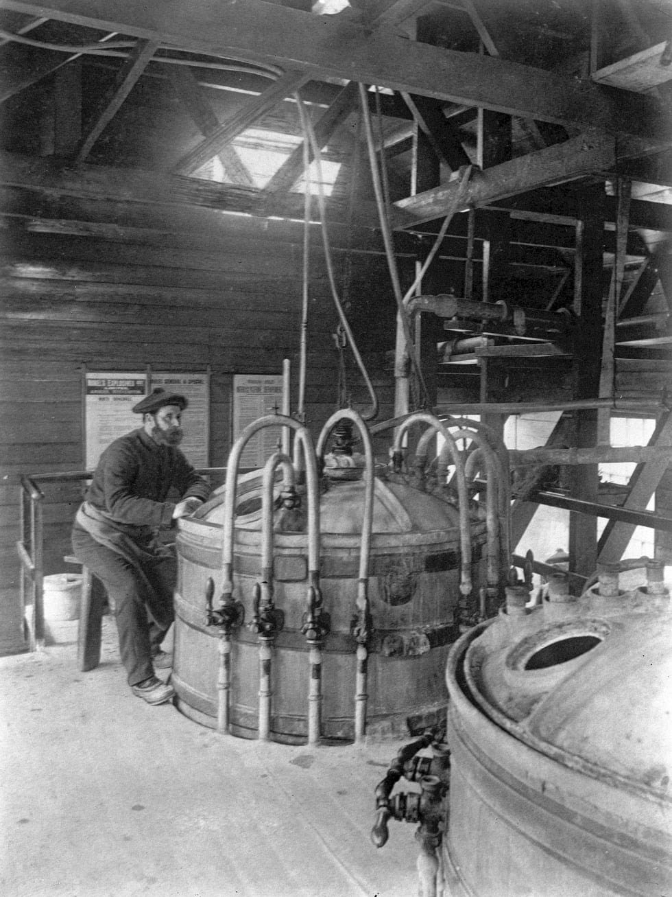
The picture, from 1887, is of an operator watching the thermometer on a reactor making nitroglycerine and adjusting the cooling water as necessary to control the exothermic reaction. The stool only has one leg, so if he dozed off, the fall would wake him – a process control system with an alarm.
Even this control system would not have been possible without the invention of the thermometer. Early thermometers were crude and often did not agree with one another. They typically had only 12 “degrees of hotness”. That was changed by Gabriel Fahrenheit (1686–1736) from 1717. With mercury (which expands well and has a good liquid range) and precision bore tubing, he was able to manufacture thermometers which were reproducible and readable to a greater precision than others. For the bottom of the scale, he chose a mixture of ice and salt – then the main method of producing low temperatures – and for the top he chose the heat of human blood. This scale was divided into 12, with each divided by two until there was a defined range from 0 to 96 degrees Fahrenheit plus extrapolation. The increased use of barometers led to a standard atmosphere being defined, and the scale was tweaked so that the ice point and boiling point of water were exactly on the scale and 180 divisions apart.
The development of measuring instruments has been a vital part of modern process control.
Early automation
In Greece in around 270 BC, prolific engineer Ktesibios invented a float valve to maintain a constant level in a tank, reckoned to be the first feedback device. This meant a stream of water leaving the tank was at a fixed rate, with the calibrated volume measuring time. Water clocks were standard until the mechanical ones of the 14th century, but went out of use, along with the float valve. The float valve was reinvented during the industrial revolution, ultimately allowing Thomas Crapper (1836–1910) to patent a ballcock and receive a Royal Warrant for his flush toilets.
In 1620, Dutch inventor Cornelis Drebbel (1572–1633) produced a feedback controller for the temperature in a chicken and duck incubator, using mercury to open and close ventilators. The same device was applied to controlling the air inlet to an oven or furnace.
The beginning of the 19th century was the age of steam, and produced many self-powered devices to keep pressure or flow relatively constant by means of moving parts against a spring or gravity, including James Watt’s (1736–1819) famous centrifugal speed governor – the rotating balls on old steam engines. In 1880, William Fisher (1856–1905), an engineer at a waterworks, worked for more than 24 hours manually adjusting valves to keep a constant water pressure for the fire service as a major fire raged. Afterwards he invented a constant-pressure pump governor in which the water opened a valve against a spring and founded a company to sell it. They are still sold today for many clean non-corrosive fluids, and Fisher Controls became a major company.
An important innovation was the bimetal strip thermostat to operate an electric switch, invented in the 1830s by polymath industrial chemist Andrew Ure (1778–1857) for use in the textile industries. It was also used for egg incubators. They are still in extensive use.
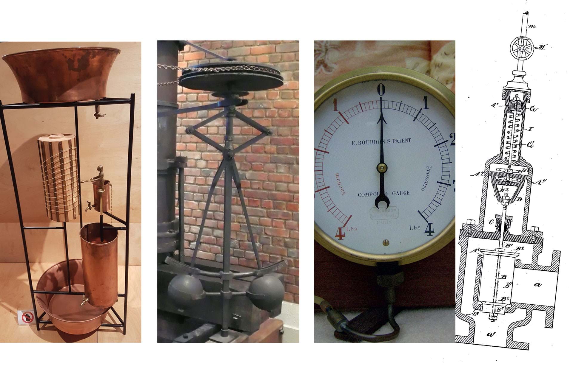
To indicate and control pressure, in 1849, Eugène Bourdon (1808–1884) patented the familiar dial pressure gauge, which contains a curved tube which tends to straighten with increasing internal pressure, and could both indicate and operate two switches, low and high. The Bourdon tube can also be used to measure temperature in a thalpotassimeter, introduced by Schäffer & Budenberg in 1884, and still in use today as a liquid-in-steel dial thermometer. A liquid in the sensing bulb exerts a vapour pressure which can be transmitted over several metres through a capillary to the dial part. Gas in steel can also be used.
In 1880, William Fisher, an engineer at a waterworks, worked for more than 24 hours manually adjusting valves to keep a constant water pressure for the fire service as a major fire raged. Afterwards he invented a constant-pressure pump governor
Air power
If the first half of the 19th century had been the age of steam, the second half was the pneumatic age. Compressed air was used to operate machinery and large valves in factories and mines, and power brakes on the railways. Small tubes carried messages and small items, larger ones carried mailbags in rail cars in which people sometimes rode, driven by higher pressure behind and lower pressure ahead. In Paris, compressed air was delivered as a utility, like electricity, via 120 miles of pipes to 1,000 businesses. The network expanded and continued up until the late 1960s. There was even a network of 7,000 public and private pneumatic clocks, with a pulse coming every minute.
Railway trains had a 70 psig system, the pressure being controlled by the air acting in opposition to a spring to close a steam supply valve to the compressor. This was the forerunner of the air-operated control valve so commonly used in chemical engineering, the first example being shown in an exhibition in Milwaukee in 1884. In this, a Ure-type thermostat operated an electric switch to open a small valve in a 10 psig air supply. This then operated the valve on a steam or fuel supply to a heating system, or a hot or cold fluid. Note, that unlike earlier constant pressure devices for steam, air, and water, this was not powered by the process fluid, and the sensor measured a totally different property. A small electric current could move a large valve some distance away in safety, and a common air reservoir could serve many valves. This was extensively used in heating applications, but was adapted for other processes as the oil industry developed in the early 1900s.
Pneumatic process control
Playing a church organ essentially means opening air valves. In 1827, organ builder Joseph Booth (1769–1834) devised a system whereby pressing a key opened a small air valve which in turn made compressed air open a big one. As well as proving less tiring for organists’ fingers, this pneumatic relay enabled practical pneumatic controllers for processes to be developed.
Movement in a sensing element resulted in it partially obstructing a jet of compressed air. This caused a back pressure which displaced a diaphragm, moving a valve operating a larger flow of air than goes through the jet. As the sensor movement was generally very small, the nozzle was tiny. In 1914, Foxboro Company made the first one using the equivalent method of vacuum, which risked blocking the jet, but subsequent ones by all companies utilised pressure. This was not merely on and off like an electrical switch, but produced a process effect according to the movement of the sensing element, though this was limited, non-linear and not understood. However, it was the beginning of a whole era of pneumatic transmission of sensor signals and ultimately complex control without any electricity – very attractive for plants with flammable materials.
It was the beginning of a whole era of pneumatic transmission of sensor signals and ultimately complex control without any electricity – very attractive for plants with flammable materials
In the century before this, the technology and theory of control had been essentially mechanical and later electrical. The oil and gas industry introduced new factors. In the 1920s, control engineers incorrectly thought speed and accuracy were critical and produced faster responses by electric or pneumatic devices to fight the hunting and oscillation common in mechanical and plant devices. By trial and error, operators modified the plant to overcome the defect in the controller, adding a tank, dashpot or flow restrictor to get more stability, with limited success and no way of predicting the results. One of these was Clesson E Mason (1893–1980) who modified the control equipment on his petroleum plant with elastic bands and springs. Joining the Foxboro Company, he studied existing theory, and added his understanding of plant behaviour to produce the first wide proportional band pneumatic controller. Users were instructed to adjust the gain low enough to limit hunting, but high enough to keep the steady-state error low. This error was typically shown by the position of a pen on a chart recorder compared with the desired line. The setpoint could be reset manually, so that while there was an offset compared with it, the actual process was on target.
Looking at flow control, he realised that it was not well served by proportional control, so carried out experiments observing what he did manually, and designed a pneumatic circuit to do this, which was called automatic reset but which we now call integral. The Stabilog controller, incorporating both, was marketed in 1931.
What we now call derivative control (then called pre-act) gives a greater response when the process is moving more rapidly. This was invented by Ralph E Clarridge (1908–1993) in 1931, based on luck and a good memory. He had mistakenly put a capillary in the feedback line of a proportional controller and got what he called a kick in the response. Later, trying to control the temperature of a wet rayon shredder, he thought that perhaps the kick would be useful and added a capillary of about the right length to create a proportional and derivative controller.
In 1940, full proportional, integral and derivative (PID) control was available in pneumatic controllers which could be field-adjusted. However, this meant three knobs to turn, largely by trial and error plus experience.
A group of mechanical engineers and physicists working in the process industries formed the Industrial Instruments and Regulators Committee of the American Society of Mechanical Engineers (ASME) in 1936 to develop common terminology and systematic design methods. In 1942, two members of the committee, John G Ziegler (1909–1997) and Nathaniel B Nichols (1914–1997) published a landmark paper providing practical ways to set the values on these controllers. The experimental work to do this used a pneumatic analogue of a process, controlled by pneumatic PID controllers. They also used a mechanical “differential analyser” to help with the difficult calculations. Mason used an electric analog computer (where mathematical equations are set up as circuits) to help with his partial differential equations. As well as controllers, he developed the equal percentage control valve and received the Oldenburger medal of the ASME for his contribution to automatic control of process plants.
There were further developments in theory and technology, but from this point pneumatic control became the standard in the oil, gas, and chemical industries. Electronic and, later, computer systems now dominate, but commonly use PID control and other techniques developed for these early systems.
However, pneumatic controllers are still used in some areas. Compressed air is commonly used to move valves, and combining this with a pneumatic controller can provide robust local control. A friend told me customers were still demanding replacement parts for systems many decades old.
One application is in the US gas industry where the gas itself is used instead of air, removing the need for air compressors.
Read other articles in his history series: https://www.thechemicalengineer.com/tags/chemicalengineering-history
Recent Editions
Catch up on the latest news, views and jobs from The Chemical Engineer. Below are the four latest issues. View a wider selection of the archive from within the Magazine section of this site.


