Energy: Using Hydrogen for Glass
Andrew Keeley and Mike Haden talk about decarbonising the glass manufacturing process using hydrogen as a fuel
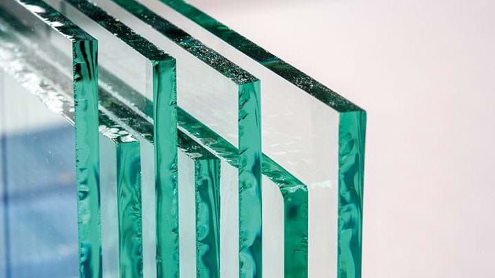
GLASS manufacturing is a challenge to decarbonise due to the high level of fossil fuel fired above the glass melt. Energy is radiated directly from the flames to the molten glass and the furnace structure. Electric heating is also used but cannot be used to replace all the direct firing without disturbing the stratified flow of the molten glass in the furnace, which is required to allow bubbles to rise to the surface.
In order to decarbonise the glass manufacturing process, we need to use a net zero fuel such as bio-fuels or hydrogen. Hydrogen comes in many “colours”: green hydrogen – made from electrolysis using renewable electricity; blue hydrogen – made from methane with the carbon dioxide captured and stored; and grey hydrogen – made from methane with no carbon capture. The trials firing hydrogen at the Pilkington UK plant in St Helens were undertaken as part of the HyNet project in the North-West of England. The HyNet project is to build a large blue hydrogen production facility to provide fuel to industry in the area with the carbon dioxide captured in redundant natural gas fields in Liverpool Bay.
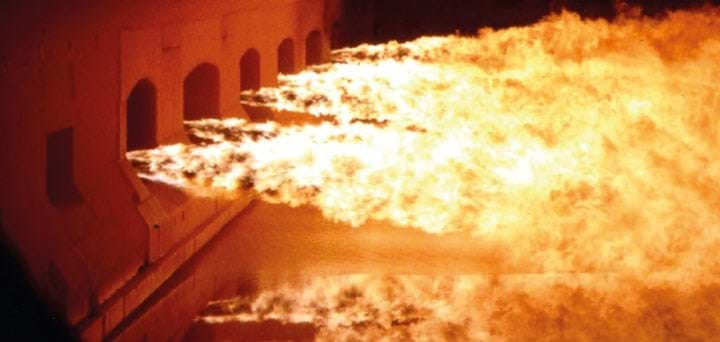
The trials were funded under the Industrial Fuel Switching programme run by the UK Government Department for Business Energy and Industrial Strategy (BEIS), to assess different industries’ ability to switch from natural gas to hydrogen. Glass furnaces are typically directly fired with natural gas or oil. Heat is radiated directly from the flames to the furnace structure and the blanket of raw materials floating on the molten glass surface. This makes the conversion to hydrogen a particular challenge as the emissivity/visibility of a hydrogen flame is low compared to natural gas or fuel oil.
Hydrogen safety is critical as the gas has a wider flammability range than methane. Hydrogen also is significantly less dense than air, having a relative density of only 6.75%, which means any leaks can lead to issues with accumulation in roof spaces. As such we did extensive smoke bomb dispersion studies around the furnace to check ventilation and installed hydrogen detectors in the main gas flow control cabin. The low density of the hydrogen also led to a significant increase in fuel flows on the burners to ensure that we maintained the same energy input. The furnace typically fires around 5,000 m3/h of natural gas, which would increase to >15,000 m3/h of hydrogen if we converted the whole furnace.
The conversion to hydrogen (is) a particular challenge as the emissivity/visibility of a hydrogen flame is low compared to natural gas or fuel oil
As part of this programme a trial was undertaken converting one port of the furnace to allow hydrogen to be added to the natural gas to assess the impact of increasing proportions of hydrogen on the combustion in a regenerative glass furnace.
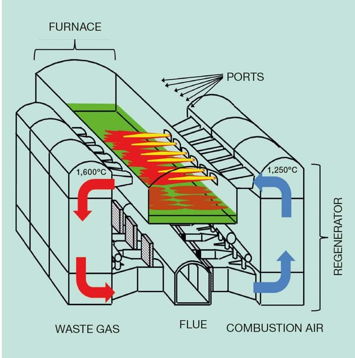
A cross-fired regenerative glass furnace manufacturing float glass is typically between 10–13 m wide and 30–40 m long, with flames covering around half of this length. The furnace operation requires heat release across the width of the furnace to uniformly melt the blanket of raw materials floating on the surface of the glass. The system works on a periodic cycle (usually 20 min). The combustion air is fed into a hot regenerator and passes through the checker pack, gaining heat from the hot bricks. The combustion air passes from the checker pack into the furnace through connections (ports). Fuel is introduced to the air stream at the port/furnace connection with flames extending across the surface of the melt. There are several of these ports along the length of a furnace, the first port being the one nearest to the raw material entry point and numbered sequentially from that point. The waste gases from the combustion process then pass down the opposite regenerator checker, heating the checker pack before entering the flue/chimney.
Significant modifications to the fuel delivery system to port 1 were made to accommodate various proportions of hydrogen mixed with natural gas, up to 100% hydrogen. Over the course of several days the proportion of hydrogen was increased, firing each proportion for ~3 h. The hydrogen was delivered to site in tankers at 228 bar pressure and was let down to 0.5 bar to match the pressure of the natural gas at the mixing point. At 100% hydrogen flow on port 1 we were using a tanker every 40 minutes.
Prior to the trial, extensive CFD combustion modelling was done to establish suitable firing setups to maximise the chances of the trial’s success. The burners were modified to maintain similar flame lengths for different proportions of hydrogen and natural gas. The visible part of a natural gas or oil flame correlates with the soot concentration in the CFD model. As the proportion of hydrogen in the fuel increases, the soot concentration drops and visibility decreases. Figure 2 compares the model predictions with the actual flame appearance as the proportion of hydrogen was increased up to 100%. It shows that the soot prediction in the model is a good representation of the flame luminosity.
As the proportion of hydrogen was increased, the flames became visibly less luminous and became effectively invisible for flames with 70% hydrogen and above, by volume. In terms of energy, however, 70% hydrogen by volume only accounts for 42.8% of the energy input with the majority still being supplied by natural gas. The proportion of hydrogen was ultimately increased to 100%, with effective melting of the batch blanket achieved.
One of the concerns about the use of hydrogen was that we would see a significant increase in NOx emissions associated with the higher flame temperatures. The intention for the trial was to keep the combustion stoichiometry constant across the different hydrogen proportions. However, this proved impractical.
The combustion stoichiometry did change over the course of the trial and this will affect the amount of NOx produced. The excess air (XSA) increased over the trial but the NOx increase overall was close to the model predictions, allowing for the change in stoichiometry.
The temperatures in the glass furnace are high enough that the changes to the flame temperature of the combustion has only a minor contribution to NOx. This is contrary to lower temperature combustion where flame temperature is a major contributor. Whilst this was valid for natural gas the effect of the increased flame temperature with hydrogen combustion needed to be assessed.
Recent Editions
Catch up on the latest news, views and jobs from The Chemical Engineer. Below are the four latest issues. View a wider selection of the archive from within the Magazine section of this site.


