Seven Deadly Sins
A guide to avoiding some of the most common mistakes in pressure relief system design
PRESSURE relief devices protect equipment from excessive under- and over pressure. The calculations and design methods employed are no different to those used in other areas of process and mechanical engineering. However, it is a specialist area, and although the broad strokes are familiar, there are many pitfalls for the unwary to fall into.
This article covers seven areas where, in our experience, mistakes are commonly made. This is by no means a complete review of pressure relief and there are other areas equally worthy of discussion that aren’t covered here. Hopefully though, it provides some useful information and will help engineers learn from others’ mistakes, rather than making their own.
1. Relief cases not adequately identified
Where did the pressure come from?
Identifying the potential causes of under- and over pressure is the most critical step in any pressure protection study. If the defining cause is missed, then all the subsequent time and expense may be pointless as the relief stream will be undersized and the equipment will be at risk. With this in mind you would suspect that this would be covered extensively in guides and standards but the reality is the opposite. There is a simple reason for this: each and every pressure system is unique and needs to be assessed on that basis, so it is very difficult to write an all-encompassing guide.
Perhaps the most widely-used standard for this area of pressure relief is API 521 – Pressure-relieving and Depressurising Systems – whose Table 1 provides a list of 17 common causes of under and over pressure, covering utility and instrument failures, chemical reactions, fires and maintenance, amongst others. However, be aware that this table “is not intended to be all inclusive or complete in suggesting maximum required relieving rates; it is merely recommended as a guide.”
These are wise words and it would be foolish for any standard to claim to provide an all-inclusive list. Another consideration is that API 521 is an oil and gas standard, published by the American Petroleum Institute, so if you are working in another sector of the industry, some parts of the common relief cases provided in its table may be irrelevant. All of this does leave the user with a problem – how to identify all of the relief cases? We have seen some companies tackle this issue by producing their own version of API’s table, deleting occurrences that are not relevant and adding ones that are. Despite best efforts, this still leaves the issue of ensuring that all relevant cases have been identified.
A pragmatic way of tackling this is to step back and look at the fundamentals of how pressure can rise. Within a pressure system, one or a combination of the following needs to occur:
- energy is input to the system (often assumed to be fully blocked in) from an external source (eg fire);
- energy is generated by the substances inside the system (eg exothermic reactions); and/or
- mass enters the system (eg high pressure breakthrough through a control valve).
To assess for under pressure, which is very much the poor relation of over pressure, the list above holds in reverse. As a word of warning, there is a subtlety that needs to be remembered with under pressure. The problems actually stem from excessive external pressure, which can buckle the system. Normally the case is a negative pressure inside the system, for example due to condensing steam. However, consider a system that has a separate system surrounding it – the engineer also needs to assess the impact of high pressure in the surrounding system placing excessive external pressure on the internal one. A real example of this is plastic storage tanks with an integrated bund. If the bund is at a high level and the tank is emptied, then the static head of the liquid in the bund will place an external force on the tank. If that force is too high, then the tank will buckle in the same way as if a vacuum had been pulled in the tank; the vessel experiences the same forces in both scenarios.
The next step is identifying what can cause these pressure excursions. For the scenarios discussed above to occur, then something has to have gone wrong. At a high level, typical events are:
- external fire;
- process abnormalities (eg high cooling water temperature);
- equipment and services failures (eg control valve failure); and
- changes in ambient conditions.
Combining these two lists produces a matrix as shown in Table 1. A matrix like this provides a more generic tool to identify causes of under and over pressure rather than a set checklist, which after all, will always have a ‘miscellaneous’ or ‘other’ section at the bottom, be it implicit or implied. Although, this is not a silver bullet, and it requires engineering knowledge and judgment to correctly identify all relief cases. It does however, provide a good starting point for an assessment.
There are some other considerations that need to be accounted for when undertaking an exercise such as this.

Operating modes
One of the most common errors when identifying relief scenarios is to believe that the plant is in normal operation and assess it on that basis. The reasons for this are obvious: the heat and mass balance is written on this basis; it is the most common operating mode; and it is how the engineers tend to envisage the plant. However, where applicable, all of the operating modes of a plant need to be considered including:
- startup;
- shutdown;
- cleaning/maintenance;
- regeneration cycles; and
- swapovers (changing flow from one item of equipment to another).
Therefore the engineer needs to assess all operating modes the plant may see
But that will never happen at the same time!
One of the most dangerous statements in API 521 is the “Double Jeopardy Rule”. Experience shows just how easily relief cases can be dismissed by this rule, often without a full understanding of its true meaning. The current rule, which is much more detailed than previous revisions, states: “The causes of overpressure are considered to be unrelated (ie independent) if no process or mechanical or electrical linkages exist among them or if the length of time that elapses between possible successive occurrences of these causes is sufficient to make their classification unrelated. The simultaneous occurrence of two or more unrelated causes of overpressure (also known as double or multiple jeopardy) is not a basis for design.”
One of the most common errors when identifying relief scenarios is to believe that the plant is in normal operation and assess it on that basis
It goes on to provide examples of double jeopardy, including: a heat exchanger subject to external fire, coincident with internal tube failure; and operator error leading to a blocked outlet, coincident with a power failure. Single jeopardy is also demonstrated by the example of instrument air failure to a vessel exposed to external fire, if the fire could cause said air failures. Despite stating that double jeopardy is “not a basis for design”, there is also a caveat that: “The user may choose to go beyond these practices and assess multiple jeopardy scenarios, particularly for severe consequence events. Because such assessments are outside the basis for design, the user is not required to meet accumulations allowed by the pressure design code for these scenarios. Acceptance criteria are the sole responsibility of the user.”
So why is this so dangerous? One reason is education; there is a common misconception that double jeopardy scenarios are never considered in relief studies, despite the new guidance quoted above in API 521. The second reason is a problem of definition; what is a double jeopardy scenario, and what is not? Consider an over pressure case that requires both a level switch to fail simultaneously with a high liquid charge or level. This could be, and has been deemed, double jeopardy: two unrelated events need to happen; two different instruments fail. But consider that the level switch was already be in a failed state. How would you know that the switch had not failed straight after its last test? If there is no way of knowing, then this is not a double jeopardy scenario.
API 521 covers this ground using the term “latent failures”, using the example of a check valve failing and allowing reverse flow in the event of a downstream pump failing. Another way of thinking about this is using the terms “discoverable” and “undiscoverable” to refer to causes. For items of equipment that can fail, or for process upsets that cause pressure excursions, ask the question: “how would the control room know it has failed?” If there is no means for an operator to identify something as not operating correctly – an undiscoverable failure – then for relief scenario identification purposes, it should be assumed to be in a latently failed state. Pressure relief is an exercise in pessimism.
Risk-based scenario identification
Engineers are increasingly using risk-based methodologies such as consequence matrices to make decisions, especially when it comes to safety. This produces a tension between how engineers handle pressure relief scenario identification and how they handle other safety-related issues. Pressure relief scenario identification identifies hazards, ie what can cause a relief event. At no point do the standards require the probability or the consequence of the over pressure to be assessed. We have heard this discussed in conversations about relief scenarios with comments such as “well it would pass a LOPA (layer of protection analysis)” as a reason for discounting a scenario (single jeopardy). The answer to this is “maybe, but the equipment design codes and relief standards require you protect the equipment from all causes of under- and over pressure”. This approach does lead to a conservatism in designing and sizing devices, but given these devices are the last line of defence against excessive pressure, is this such a bad thing?
Another argument for taking a conservative view of hazard identification is to consider that incidents normally occur when more than one thing has gone wrong. For example, the operators may have had to perform an unusual operation due to production issues or one or more items of equipment may be in a latently failed state. Remember that a designer can never fully understand what an operator will do with the plant once it is operational!
However, risk-based judgements are starting to creep into relief standards. One example is the use of a temperature-corrected test pressure for shell-and-tube heat exchangers. The premise of this rule is that the over pressure caused by a tube rupture will put less stress on the equipment than it saw during its pressure test, so we have confidence that the exchanger will not catastrophically fail.
Something to note from the current version of the double jeopardy rule is that users may choose to “assess multiple jeopardy scenarios, particularly for severe consequence events.” This is requiring engineers to identify severe consequence events such as releases of toxic gases and to consider whether the probability of the event is acceptable versus the consequences, which is a risk-based approach.
2. Relief device sizing
Once the relief scenarios have been identified, and the relief rates have been calculated, the size of the relief device needs to be determined. There are equations for determining the required relief area in many different standards and, although they may look slightly different, they are all fundamentally the same equation, the differences being the units of measurement and the number and format of correction factors included. The critical vapour sizing equation from API 520 part 1 – Sizing, Selection and Installation of Pressure-relieving Devices – is:
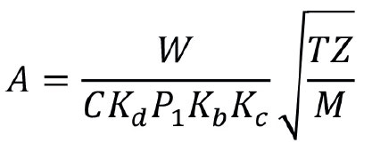
where A is the effective discharge area (mm2), W is the required relief flowrate (kg/h), C is a function of the ideal gas specific heat ratio, Kd is the discharge coefficient of the relief valve, P1 is the upstream relieving pressure (kPa), Kb and Kc are corrections for back pressure and bursting discs, T is the temperature of the vapour (K), Z is the compressibility factor and M is the vapour molecular weight.
Although the equation itself is simple enough to understand and the inputs should be known from the calculation of the required relief rate, there are a couple of areas where mistakes can occur.
The most common mistake we’ve seen is the choice of value for Kd. The discharge coefficient is a value measured by vendors when they are manufacturing a make and model of relief device. The reason for this correction factor is that valves do not behave like perfect orifices, which would be represented with a Kd of 1. There are frictional losses that occur as the fluid passes through the valve nozzle and body which reduce the flow, and thus a correction factor needs to be implemented in the equation. The errors are introduced when engineers are using API 520 part 1 which provides preliminary values for Kd – 0.975 for vapour relief valves; 0.65 for liquid relief valves; and 0.62 for bursting discs. Despite API clearly stating that this is for preliminary sizing, many engineers use these values because “API says so”. API does not, and as far as I know, will never manufacture relief devices. These suggested values are reasonable for initial sizing estimates, but there has to be a final check on the selected valve for both its orifice size and Kd, which is a step that isn’t always completed.

Table 2 shows a list of actual Kd values from a variety of makes and models of relief valves. The important point to note is that they are all different, some closer to the API 520 value than others.
The relief valves shown have relatively high Kd values, but they can be much lower. One of the reasons for this is the lift of the relief valve, which is the distance between the nozzle and the valve seat. When relief valves are sized, it is the orifice area that is determined, which is shown in green in Figure 1. For high lift valves (high Kd value valves) the orifice is the minimum flow area and defines the flow. However, for low lift valves it is the curtain area (shown in purple in Figure 2) which is the minimum flow area. Valves are specified using orifice areas, not flow areas, so the valve shown in Figures 1 and 2 will have a low Kd, and if the engineer has used a value of 0.975 in their calculations then the valve will be undersized by a significant factor.


Bursting discs
The same equations can be used for bursting discs as well as relief valves. Manufacturers can provide discharge coefficients as well as flow resistance values such as K factors, to be used in fluid flow models. The issue with bursting discs is that the normal sizing equations only provide an initial sizing estimate. When considering gas or vapour relief, the capacity of the relief stream is dependent on the first choke within the system. For relief valves, this occurs across the valve orifice by design. For bursting disc systems it is unlikely that a choke or pressure discontinuity will occur across the bursting disc – this capacity-determining phenomenon will occur elsewhere in the pipework system. Therefore the whole relief system needs to be modelled with the correct flow resistance for the bursting disc, to ensure that the relief capacity of the system is greater than the required relief rate. Once the capacity of the system has been determined, API requires this capacity to be multiplied by 0.9 or less to allow for uncertainties. This requirement can often be overlooked by engineers.
Ideal gas assumption
The standard equations used for gas and vapour relief device sizing are built on an assumption that the fluid is behaving as an ideal gas and although many vapours do not follow the ideal gas law, pressure relief devices are adequately sized on this basis. As such, there are a couple of areas which the engineer needs to be mindful of. The variable C in the area equation is determined from the ratio of specific heats for the fluid and the ideal specific heat ratio should be used. The other thing that engineers need to keep in mind is the value of Z, the compressibility factor. If Z is less than 0.8, which can occur in high temperature, high pressure systems, then the standard sizing equations can produce significant errors. Alternative sizing methods – such as those described in Annex B of API 520 part 1 – should be used at this point.
3. Materials of construction
It is a fairly obvious statement to say that a relief device should not have its operation impaired by chemical corrosion of the wetted parts. The question is, what are the wetted parts? For a relief valve the inlet nozzle and the disc are obviously in contact with the process fluids and should be suitable for the duty. The engineer needs to realise that relief valves are not intended to be leak tight and thus process fluids can and will seep into the body of the valve. This can be simply demonstrated by API 527 - Seat Tightness of Pressure Relief Valves - which describes methods for determining the leak tightness of such devices and the acceptance criteria. For example, a metal seated valve with a set pressure of 14 kPa and an orifice diameter less than 18 mm should have a leakage rate equal or less than 0.017 m3 per 24 h. This isn’t a lot of fluid but it is more than zero. Therefore the wetted parts of a relief device must include nozzle, disc, stem, bellows, and soft goods.
A good example of where incorrect material of construction can cause issues is balanced bellow valves. Typically the material of construction of the bellows is stainless steel, as it is cheaper than more resistant materials such as Inconel. The bellows are critical for the performance of the valve in order to withstand built-up back pressures and variable superimposed back pressures. However, if there is a failure of the bellows (see Figure 3), then the valve effectively acts as a conventional type valve potentially leading to maloperation at the time it is required.
Chemical resistance is not the only consideration when choosing materials of construction. For example, in systems where auto refrigeration is significant, the valve needs to be adequate for the outlet temperatures of the fluid.

4. Piping design
Pressure drops
Most engineers know that there are pressure drop limitations around relief valves, typically 3% of the set pressure on the inlet and 10% of the set pressure on the outlet. The reason for this is stability and reliability of the valve in operation. A relief valve works by a simple force balance across the seat of the relief valve. When the valve is closed the ‘downwards’ or closing force is provided by the spring and any pressure in the body of the valve. The ‘upwards’ or opening force is provided by the pressure of the process fluid acting over the nozzle area (force = pressure x area). When the valve opens, two effects can alter this force balance and cause the valve to reseat.
The first is loss of inlet pressure, the fluid is now flowing and frictional losses will reduce the pressure so that the opening force is decreased. The second is increased pressure in the body of the valve, increasing the closing force. Relief valves are designed to cope with these effects: the seat area is larger than the nozzle area so that the flowing fluid acts over a larger area, providing more upwards force when open compared to when closed. The engineer should be careful not to blindly use 3% and 10% for the pressure drop acceptance criteria. These are common and typical numbers, but there are relief valves on the market which are different – for example some valves will only accept 5% backpressure.
Line sizing
As well as pressure drop criteria, there are also some simple design rules that the engineer is required to comply with. The nominal pipe diameter of the inlet piping should be no less than the valve inlet size (unlike that shown in Figure 4!). This includes all elements of the pipework, so for example if an isolation valve is installed, it should be full bore. The criteria becomes more interesting if other piping components are used which are not full bore. For example, there may be a bursting disc in the line with a vacuum support. In this case the free flow area through these devices should be the same or larger than the free flow area into the inlet of the valve. There are two reasons for this, firstly meeting the 3% inlet pressure loss criteria and secondly to ensure that the valve is determining the capacity of the relief system rather than another piping component.
For the discharge line API does not provide a similar line size requirement. Appendix M of ASME VIII – Rules for Construction of Pressure Vessles – does state that the discharge pipe shall be at least of the same size as the valve outlet, which matches European codes that explicitly state this requirement. The simple fact of the matter is it is very difficult to get a backpressure of less than 10% with pipework smaller than the valve outlet. If engineers are undertaking the preliminary design of a relief system, we recommend going one size up on the pipework either side of a relief valve in order to meet the pressure drop criteria both now, and for potential future modifications.
Valve installation
Typical relief valves should be installed in a vertical position, with the spring acting towards the ground. This is simply because they are designed to be installed in this orientation, and if they are horizontal they may not open and close as designed. The vast majority of relief valves are installed in the correct position, but there are examples where space constraints or line pressure drops have led engineers to install them horizontally. Figure 5 shows one such valve which was installed horizontally on an air compressor. Vibrations caused the spring to erode the metalwork to such an extent that it protrudes through the bonnet, rendering it useless. This is an extreme example, but demonstrates the point very well.

Practical considerations
There are a host of other considerations to observe when sizing and designing the relief pipework. In general, lines should be as short and simple as possible, and be suitable for all possible relief cases. They should be chemical, pressure and temperature compatible and attempt to eliminate low points and dead legs in order to reduce corrosion and possible blockage.
One common issue is a buildup of water in the pipework downstream of the valve. Water can collect due to rainfall, but it can also form through condensation. This water should not be allowed to collect on the discharge side of the relief device, as it will cause operational issues. Typically, drain holes are provided at a suitable low point. Some installations try to eliminate rain ingress through a variety of devices installed on or near the discharge pipe exit. Engineers need to consider carefully the effect of these devices on the relief flow.
Typical methods for eliminating rain ingress are weather cowls and swan necks on the outlet. However, these devices will direct the relieving gas and vapour towards the ground, which if flammable or toxic, may not be desirable. A rarer form of protection is to place something on the end of the pipe such as metal or plastic caps, or elastomer bags (see Figure 6). Again the engineer needs to consider the impact of these devices on relief events:
- increased back pressure in the system;
- devices corroded or stuck to the discharge pipe, reducing the discharge capacity; and
- devices becoming projectiles if unrestrained, creating another hazard on site.

5. Pipe supports
Pipe supports can be the forgotten element in a successful relief system design, as typically there is no flow through these systems. Hopefully the relief system isn’t required to work, but when the relief event occurs, the pipework has to transport the fluid to the relief device and then to the safe discharge location. The forces that act on pipework in a relief event can be substantial, so the designer has to determine these and provide adequate pipe supports.
The forces that act on pipework in a relief event can be substantial, so the designer has to determine these and provide adequate pipe supports
Reaction forces are made up of two elements. The first element simply follows Newton’s Third Law that every action has an equal and opposite reaction; there is a fluid passing through the relief device and pipework, resulting in an equal and opposite force on the pipework. The second element is pressure related. If there is a choke point, ie the gas or vapour is travelling at sonic velocity, then a pressure discontinuity will be created. This is a point where the fluid pressure suddenly changes, and since, for the same area, force is proportional to pressure, the forces on both sides of the pressure discontinuity will be unbalanced, leading to a resultant force on the pipework.
API 520 part 2 contains equations to determine this force, and vendors will normally quote a value for their devices. However API 520 part 2 also states: “…large forces may result if there are sudden pipe expansions within the system or as a result of unsteady flow conditions during the initial activation of the relief device.”
API 520 part 2 refers the user to ASME B31.1 – Power Piping –and ASME B31.3 – Process Piping – for the design of piping systems to withstand reaction forces from pressure relief devices. ASME B31.1 contains a section on “Dynamic Amplification of Reaction Forces”, which is presumably what API 520 part 2 is referring to. The internal forces and moments within a piping system are generally larger when the loads in the system are varying with time, as opposed to those produced under a static load. ASME B31.3 contains the term “dynamic load factor” (DLF), which has a value between 1.1 and 2 and can be calculated if the engineer knows the valve opening time, although this is not normally readily available. The forces determined by the appropriate calculations should be multiplied by a DLF to determine the maximum force that the pipework will experience in the initial opening of the relief valve. If engineers are using vendor-supplied figures for the reaction force then they should check whether a DLF has been used or not.
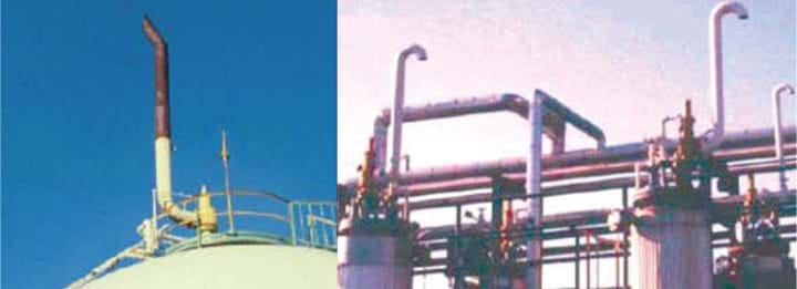
A simple check is to physically look at your discharge pipework. If it looks like the pipework in the pictures (see Figures 7–8) they may need some urgent redesign!
6. Codes and standards
When designing pressure relief systems, engineers will naturally reach for common standards such as API 521. This is definitely a good place to start, as it contains many of the considerations and information that will be needed. What engineers miss, is that the equipment they are protecting is also designed to a code which is very likely to have its own rules about excessive under and over pressure. API 521 is based on ASME codes, specifically ASME VIII, but if your equipment isn’t designed to this there may be important elements being missed out in the design.
A good example of this is the allowable accumulation, the pressure above design pressure or maximum allowable working pressure (MAWP), that the equipment is allowed to experience in an emergency situation. ASME VIII will allow 10%, 16% or 21% depending on the situation and the relief system configuration. European vessel codes limit accumulation to 10%. There is a European cryogenic vessel design code which allows relief devices to be set at the test pressure, rather than the MAWP. ASME I has very different rules to ASME VIII on allowable installation configurations and accumulations.
The key is that the final relief system needs to fulfil the requirements of both the equipment design code and the relief device design code.
The key is that the final relief system needs to fulfil the requirements of both the equipment design code and the relief device design code
The other area to be wary of is that not all relief valves are designed to a standard specification, for example, ASME, API 526, or EN 4126 part 1 etc. These tend to be cheaper, brass, low-lift relief valves for utility systems. The criteria used in API 520, such as maximum built up back pressure of 10%, are typical numbers based on valves designed to ASME or API codes. Engineers need to check the details of the actual device being installed.
The final comment to make is that meeting the requirements of the standard does not guarantee the system design is correct and will operate as intended. All codes, standards, and guides are based on good practice and engineering experience, but cannot cover all applications and situations. As an example, take a look at the often-overlooked Special Notes section in API 521: “These publications are not intended to obviate the need for applying sound engineering judgment regarding when and where these publications should be utilised.”

7. Discharge locations
Passing a fluid through a safety device such as a relief valve does not make it safe. Thought needs to be given to where the fluid is going to end up and engineers need to know what “to a safe location” written on many P&IDs actually means.
The first consideration regards the fluid that will be discharged. What phase is it – gas, vapour or liquid? What hazardous properties does it have – flammable, noxious, toxic? Other less obvious considerations may also be required such as noise, light pollution or odour. Once these have been identified then the appropriate discharge location can be identified.
Typically, gas or vapour releases are taken to a high point and released to atmosphere via a vent or a flare. If it is a liquid relief, then it needs to go back into the process or to a liquid collection system. Two-phase relief needs effective separation with the gas and liquid each going their separate ways. This can go wrong when space is tight and we have seen relief systems where this final step has not been fully considered. For example, steam relief valves that discharge onto walkways at knee or even face height; explosion panels that exit a building next to the access door; discharge points that have pipework routed above them which will disrupt the dispersion and may direct hazardous material back down to the ground.
It is best practice to audit a newly-installed relief system before it is commissioned to ensure that the delivered solution matches the design. The discharge point is one area that engineers should review, as the engineering drawings used in the design won’t necessarily tell you where to put that discharge point. Just ask yourself, would you stand next to that system in Figure 9 if it went off? If not, then why should somebody else?
Conclusion
It is all too easy to overlook some of the multiple and varied considerations necessary when designing a relief system. Whilst it is true that other protective measures will catch the majority of problems before they escalate, these systems do sometime fail. Relief systems are intended as a last line of defence against potentially catastrophic events, and so every effort should be made to ensure that they perform on demand, regardless of the cause of time of failure. To echo words from the introduction, let’s learn from others’ mistakes, rather than making them again.
Recent Editions
Catch up on the latest news, views and jobs from The Chemical Engineer. Below are the four latest issues. View a wider selection of the archive from within the Magazine section of this site.


