Rules of Thumb: Heat Exchanger Selection
Stephen Hall discusses the golden rules for design
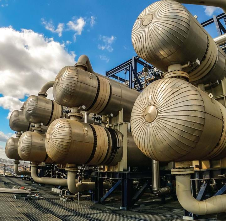
HEAT exchangers are critical elements in every process plant. Project engineers are responsible for determining the performance requirements and specifications. Specialty manufacturers then design and fabricate the exchangers in accordance with the specifications. I enthusiastically recommend to specifying engineers that they expend the effort to fully understand their heat transfer applications before engaging equipment manufacturers. This reduces the chances that the manufacturer provides a suboptimal design or, worse, that the engineer specifies the wrong type of exchanger.
- Consider these factors when choosing the type of heat exchanger to use for a particular application:
- Operating conditions – service requirements (eg phase change), thermal duty, and temperature approach.
- Cleanliness of the streams.
- Maximum design pressure and temperature.
- Heating or cooling application (or both).
- Maintenance requirements.
- Material compatibility with process fluids – wetted surfaces and gaskets.
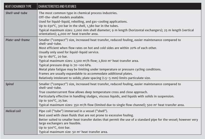
Use Table 1 to make a preliminary selection of the exchanger type. Answer the questions listed below, if applicable. Tabulate the performance criteria (I recommend the use of a datasheet, see Table 2). Then, you are well-prepared to engage vendors.
I enthusiastically recommend to specifying engineers that they expend the effort to fully understand their heat transfer applications before engaging equipment manufacturers
Here are guidance questions (Hall, Rules of Thumb for Chemical Engineers, 6th Ed, Elsevier, 2018).
- Which of the following parameters can float? To close the heat balance, one parameter is determined from the other five: hot and cold stream inlet temperature, outlet temperature, and flow rate. The answer is often flexible, meaning that two or three of the parameters may be safely varied within ranges. (“Float” means that if there are six parameters, any five of them can be changed which will affect the sixth. Five degrees of freedom.)
- What variation in temperature of the fluids is anticipated? This is particularly pertinent for cooling tower water that has a temperature that varies with the outside dew point temperature.
- What are the maximum allowable pressure drops through the equipment for the two streams? Ensure that unintended vaporisation is avoided as the pressure is reduced through the exchanger.
- Are there conditions that could result in freezing, precipitation, or extraordinary fouling? If the hot stream flow is stopped while continuing the cold stream flow, what would happen as the temperature of the stagnant fluid in the heat exchanger cools?
- Similarly, what outcome is expected if the cold stream flow stops without interrupting the hot stream?
- Are thermodynamic properties for both streams available, or can they be predicted from the properties of pure components?
- Is a temperature cross expected and, if so, can it be avoided? A temperature cross occurs when the outlet temperature of the hot fluid is lower than the outlet temperature of the cold fluid. It is physically possible in true countercurrent equipment such as a spiral heat exchanger, a double-pipe exchanger, and single-pass type BEM shell-and-tube unit. In many instances though, to use shell-and-tube equipment, multiple shells are required to allow a temperature cross.
- Are there physical limitations? Consider the available space for installation (including logistics of rigging the exchanger into place), maintenance (with an allocation for removing tubes), and elevation requirements (the relationship with associated equipment such as columns and pumps).
- Is this a batch or a continuous process? Operating efficiency, in terms such as pumping cost and maintenance, is usually more important for exchangers that are in continuous operation for months, or years, between shutdowns. Batch, or intermittent, processes may stress the exchanger with thermal and pressure changes every time the unit is started and stopped.
- How will the fluid flow rates be controlled? If it is planned to control the flow rate of the cooling water, for example, a reduction in duty due to process variations, or a lower-than-planned cooling water flow rate due to oversizing the exchanger may result in excessive fouling.
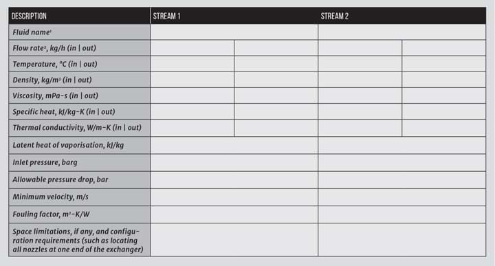
Table 2 lists the minimum data that the engineer’s specifications should include. The manufacturer will provide physical properties unless the fluids are unusual.
Determine the “allowable” pressure drop from the context into which the exchanger and its two streams are installed. For example, if a cooling water stream is returned to a common header, the pressure drop through the exchanger may be constrained.
The fouling factor accounts for performance degradation over time. Various mechanisms may deposit material on the tube or plate wall and inhibit heat transfer. The manufacturer will calculate a “clean” and “dirty” duty; these values relate to the condition with no fouling and complete fouling as specified.
The more common fouling mechanisms are: crystallisation, sedimentation, biological growth, chemical reaction coking, and corrosion. In tubular exchangers, the fouling factor may range from 0 for extremely clean fluids, such as pure steam, to 0.001 m2K/W for heavy oils. If in doubt, start with 0.0002 if the velocity is greater than 1 m/s or 0.0004 for lower velocities. For similar services, a plate exchanger will have a fouling factor that is about one-tenth of the factor for a tubular exchanger.
An alternative to specifying a fouling factor is to specify excess area. For this approach, the designer will establish the optimum exchanger configuration with no fouling, and then add extra heat transfer area – up to 20% - without changing critical design choices. This is typically accomplished by adding length to a shell-and-tube design (to maintain velocity while adding extra area) or by providing for adding extra plates to a plate-and-frame exchanger.
Due to the many independent variables, the design of a heat exchanger is sometimes considered to be an art form. But much of the mystery will be removed when you have answered the questions that I have posed
With the guidance given in this article, you should be positioned to confidently specify a heat exchanger, and intelligently discuss design alternatives and trade-offs with the exchanger manufacturer. Due to the many independent variables, the design of a heat exchanger is sometimes considered to be an art form. But much of the mystery will be removed when you have answered the questions that I have posed.
This is the twentieth in a series that provides practical insights into on-the-job problems. To read more, visit the series hub at https://www.thechemicalengineer.com/tags/rules-of-thumb
Disclaimer: This article is provided for guidance alone. Expert engineering advice should be sought before application.
Recent Editions
Catch up on the latest news, views and jobs from The Chemical Engineer. Below are the four latest issues. View a wider selection of the archive from within the Magazine section of this site.

