Rules of Thumb: Flow Parameters
Stephen Hall discusses the golden rules for design
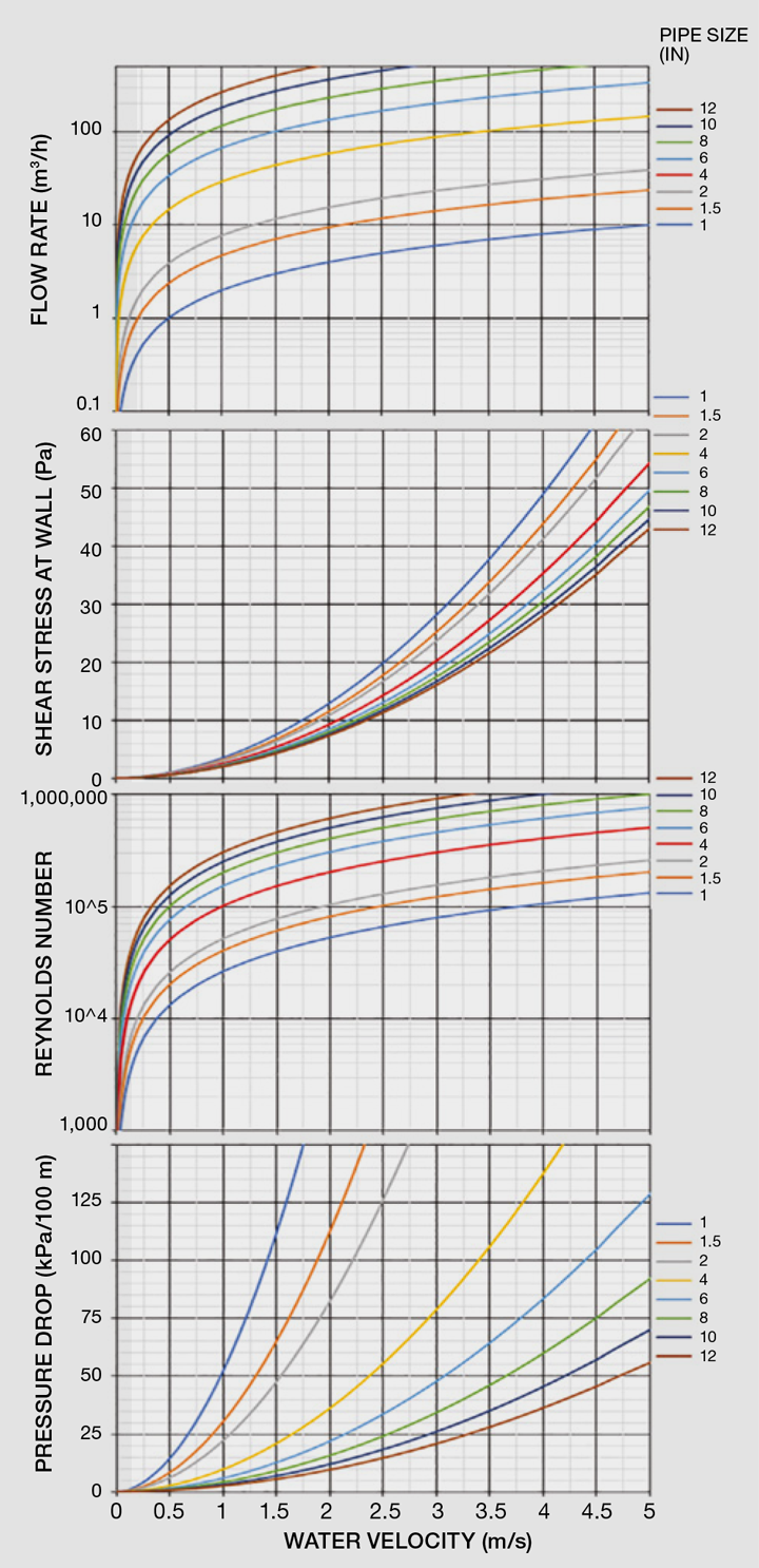
RULES of thumb are sometimes misleading. Engineers often discuss rules of thumb for pipe sizing. Velocity (1–4 m/s) and Reynolds number (>10,000) are cited, as are pressure drop (20-80 kPa/100 m) and shear stress (>5 Pa).
Given a flow rate and pipe size, these charts give a Reynolds number and velocity. The charts trace any one parameter along with pipe size and yield the remaining flow parameters.
I made these to help me visualise the relationships between flow rate and pipe size. From these charts you can see that the “rules” are not consistent. For example, if you hold velocity constant at 2 m/s, the pressure drop varies from about 10 kPa/100 m for 12-inch pipe to >125 kPa/100 m for 1-inch.
The lesson is that general sizing rules must be tempered with good engineering. Before applying a generalisation that you read on the internet or given by a colleague, take the time to understand the derivation for that rule of thumb and ensure it applies to your situation. Pipe sizing isn’t an exact science and rules of thumb are perfectly acceptable when choosing a size, but this should be done with eyes open.
Before applying a generalisation that you read on the internet or given by a colleague, take the time to understand the derivation for that rule of thumb and ensure it applies to your situation
How do you determine the pipe sizes for a system? The first step is establishing the process requirements: flow rates, fluid properties, and pipeline configuration. Many engineers then apply a rule of thumb that says to use a velocity of 1.5 to4 m/s. Higher velocities mean higher pumping cost and possibly damage to the piping due to erosion or water hammer. Lower velocities mean larger (more expensive) piping and possibly problems from fouling or solids depositions in the pipes due to insufficient turbulence.
One approach is to perform a life-cycle cost analysis that balances operating and maintenance costs against the initial capital investment. This analysis usually results in a velocity around 2-3 m/s, giving that rule of thumb. More expensive piping materials and larger pipe sizes tend to favour sizing for higher velocities whereas common materials and smaller sizes indicate lower velocities.
A rule of thumb that incorporates pipe size is to choose liquid lines to handle a velocity of 1.5 +d/10 where “d” is the pipe diameter, inches. This gives 1.6 m/s for 1-inch and 2.5 m/s for 10-inch piping, and about 20 kPa/100 m pressure drop. Similarly, gas lines can be sized for 20d m/s and steam lines 35 m/s (maximum).
Another sizing approach is based upon existing infrastructure limitations. For example, your plant’s chilled water pressure or a pump’s capabilities might limit the maximum pressure drop. However, you might not be able to provide a target of, for example, 60 kPa/100 m. Instead, the pipe sizing might simply be based on the available pressure drop regardless of how that fits into the generality.
Pharmaceutical engineers often cite “turbulence” as the driving criteria for sizing the piping for high purity water. The idea is that turbulent flow, defined as Reynolds number >4,000 (or >10,000, depending upon which engineer is speaking), greatly reduces the propensity for a biofilm to establish on a pipe wall. However, there is always a laminar layer at the pipe wall; it is many times deeper than a typical biofilm thickness even at a Reynolds number of 50,000. Studies show that microbes will tightly adhere to stainless steel pipe walls when the shear stress is less than 8-10 Pa. As seen on the charts, the Reynolds number needs to be well over 50,000 to achieve 10 Pa shear stress at the wall.
The pipe size choice may be influenced by other factors: 1) Pipes are typically one size larger on the suction side of a pump than on the discharge; 2) a smaller-than-expected size might be selected to make installation in tight quarters easier; 3) when a very small line, such as ½” or ¾”, is acceptable, the engineer might upsize it to 1” or even 2” to provide strength, so someone who steps on the line won’t break it; and 4) short pipelines will be smaller diameter than long ones with equal pressure drops.
Also consider the nature of the fluid being pumped and the material that the piping is made from. Corrosive fluids such as acids, and abrasive fluids such as slurries, will tend to be more aggressive toward the piping at higher velocities. Higher velocities will also create greater water hammer if valves are suddenly closed. If the fluid carries large particles, such as sand, the velocity should exceed the settling rate of the particles (typically about 1 m/s).
Use the rules of thumb judiciously. Let them give you a first estimate, and use them again to reality check your final selections. Pipe sizing exercises are filled with calculations, but the formulas used in those calculations are themselves based upon empirical data and sometimes fuzzy data. These notions make the whole sizing process an engineering art form, which gives my creative side great joy.
This is the fifth in a series that provides practical insights into on-the-job problems. To read more, visit the series hub at https://www.thechemicalengineer.com/tags/rules-of-thumb
Disclaimer: This article is provided for guidance alone. Expert engineering advice should be sought before application.
Recent Editions
Catch up on the latest news, views and jobs from The Chemical Engineer. Below are the four latest issues. View a wider selection of the archive from within the Magazine section of this site.


