Rules of Thumb: Centrifugal Pump Efficiency
Tom Baxter looks at how focusing on fluid efficiency can maximise cost savings while also reducing greenhouse gas emissions
ACCORDING to the British Pump Manufacturers Association, “pumps are the single largest user of electricity within industry across the European Union, consuming over 300 TWh pa of electricity, which in turn accounts for over 65m t CO2”.1 Factor in a study of industrial facilities commissioned by the US Department of Energy (DOE) which found that “a pump’s efficiency can degrade as much as 10% to 25% before it is replaced”, and that “efficiencies of 50% to 60% or lower are quite common”.2 Add their caveat that “because these inefficiencies are not readily apparent, opportunities to save energy by repairing or replacing components and optimising systems are often overlooked” and you can see why an article on centrifugal pump efficiency – the most common type of pump3 – seems appropriate.
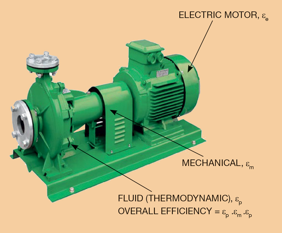
The overall efficiency of a pump and drive motor system is illustrated in Figure 1. It is a combination of electrical, mechanical, and fluid (thermodynamic) efficiency. The motor, bearings, shaft seals, and gears are all sources of inefficiency, but I will concentrate on fluid efficiency.
Theory
A centrifugal pump works on the principle of conversion of the kinetic energy of a flowing fluid into potential energy – pressure or head. This action is described by Bernoulli’s principle for an inviscid fluid.

Where:
p1 = inlet pressure (Pa)
p2 = outlet pressure (Pa)
v1 = inlet velocity (m/s)
v2 = outlet velocity (m/s)
h1 = inlet elevation (m)
h2 = outlet elevation (m)
ρ = density (kg/m3)
g = gravitational acceleration (m/s2)
Now consider a 10 m vertical pipe filled with static water that is open to the atmosphere.
v1 = v2 = 0
h1 = 0 m
h2 = 10 m
p2 = 1 bar = 100,000 Pa
ρ = 1,000 kg/m3
g = 10 m/s2 (approx.)
Therefore, the pressure at the base of the column is:
p1 = p2 + 10 x 10 x 1,000 = 200,000 Pa = 2 bar
To overcome that 10 m hydrostatic head, a pump would have to generate an outlet pressure of 2 bar. Bernoulli can also tell us the velocity that would be required to produce a pressure of 2 bar.
v2 = 0 m/s
h1 = 0 m
h2 = 0 m
p1 = 100,000 Pa
p2 = 200,000 Pa
ρ = 1,000 kg/m3
v2 can be calculated as:
v2 = (2(200,000-100,000)/1,000)0.5 = 14.1 m/s
Hence to overcome a backpressure of 1 bar, a fluid velocity of around 14 m/s would be required. That would be the velocity a pump would have to generate to overcome a 10 m head.
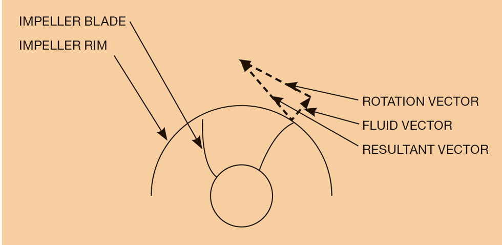
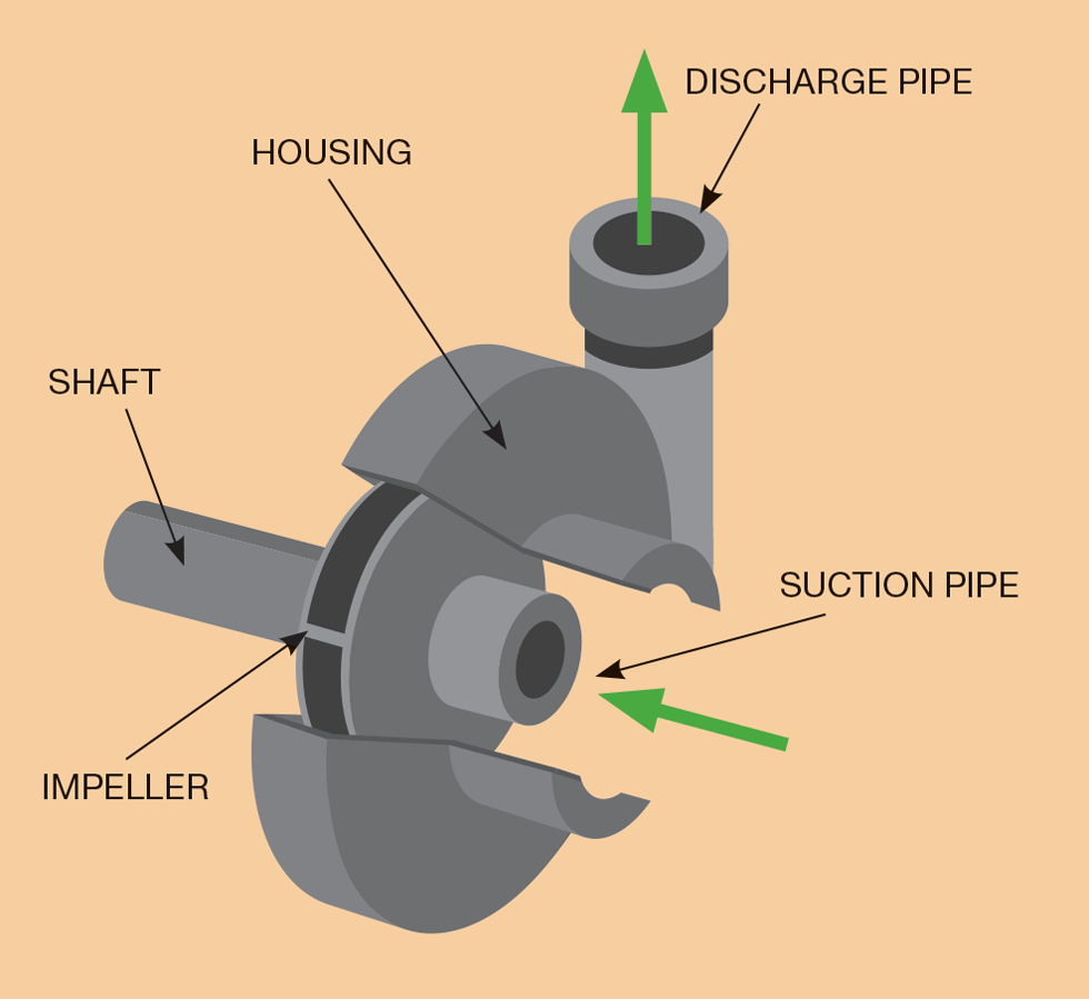
The key part of a centrifugal pump is the impeller. The rotation of the pump impeller accelerates the fluid as it passes from the impeller eye and outward through the impeller vanes to the periphery. As the fluid exits the impeller, kinetic energy is converted to potential as it slows down within the outlet pipe (volute/diffuser). The energy conversion results in an increased pressure on the downstream side of the pump.
The pump efficiency is affected by the angle and velocity at which the liquid is thrown from the impeller rim. The pump designer provides an impeller design that gives maximum efficiency at the given design rate – best efficiency point. Changing the flowrate alters the throw-off vector and hence alters the efficiency of energy recovery to head/pressure. Either side of the design point, the pump will be less efficient.
Pump thermodynamic power is calculated as follows:

For most engineering design purposes a liquid can be assumed to be incompressible, hence:

Where:
W = power (kW)
q = flowrate (m3/s)
E = overall fluid efficiency accounting for losses (-)
P1 = inlet pressure (kPa)
P2 = outlet pressure (kPa)
Clearly fluid efficiency is key to reducing the pump’s greenhouse gas footprint. This is illustrated in the following calculation. A centrifugal water pump is handling 0.092 m3/s, the suction pressure is 950 kPa and the discharge pressure is 20,000 kPa.
Pump efficiency, E = 0.75
Power required = 2,340 kW
Repeat with pump efficiency, E = 0.85
Power required = 2,060 kW
If the pump is powered by electricity derived from an open cycle gas turbine operating at 35% efficiency using methane, the CO2 emissions over a 20-year cycle would be 232,000 t with 75% pump efficiency and 205,000 t with 85% efficiency. That is a life-cycle saving of 27,000 tonnes CO2 with the more efficient pump. There would be other savings too, including nitric oxides, sulfur oxides, carbon monoxide, unburned methane, and particulates.
Pump characteristics
The fluid mechanics and energy transfer within the pump result in generic, fixed speed, centrifugal pump flow characteristics (see Figure 4).
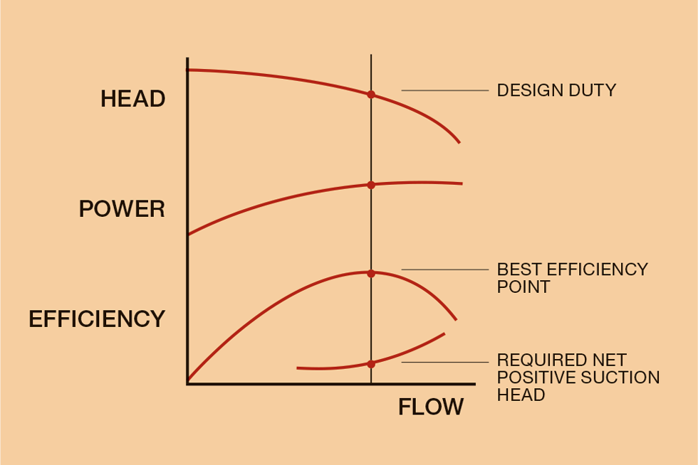
The gradients of head, power and efficiency will be dependent upon the pump design, particularly the impeller.
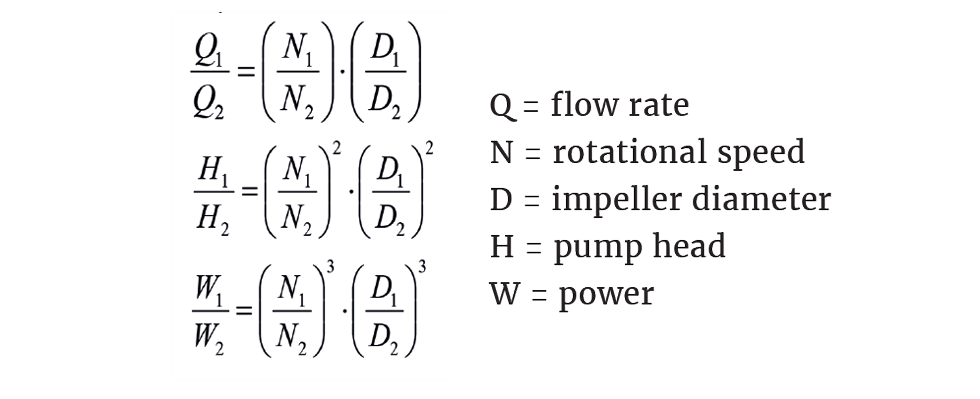
The given characteristic can be used to assess the affects speed and diameter have on flow, head and power using the affinity laws.
Pump type and efficiency
Impeller type
Centrifugal pumps are generally categorised by the impeller design: radial, mixed, or axial flow. The flow path in radial impellers follows a right angle. They have lower speeds and are primarily used for lower-flow, high-head applications.
For high flow rate, low-head applications, axial impellers (propellors) are favoured. Between radial and axial arrangements, the impeller is of mixed flow design – a combination of radial and axial.
Mixed flow impellers usually deliver best efficiencies. The impeller is often selected using the correlating parameter specific speed. Specific speed is defined as the speed of an ideal pump geometrically similar to the actual pump which, when running at this speed, will raise a unit of volume, in a unit of time through a unit of head.
Specific speed, Ns, is determined from:
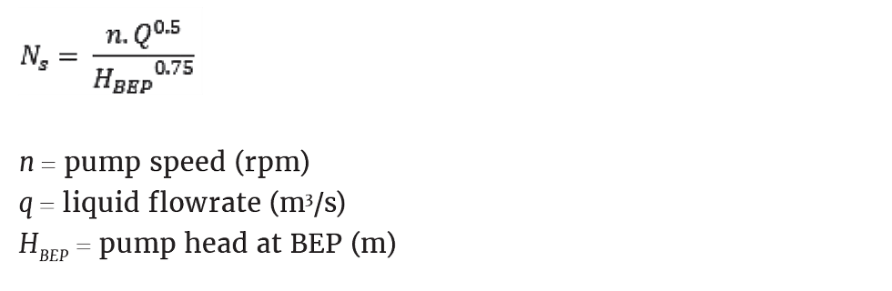
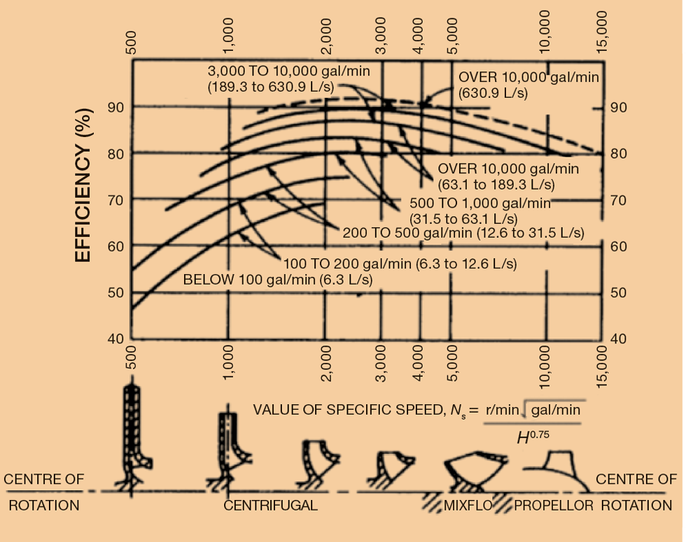
API610 Centrifugal Pumps for the Petroleum Industry sets out how efficiency varies with impeller type and specific speed (note imperial units).4
The API610 data illustrates that a mixed flow impeller is likely to be the most efficient and that the larger the pump, the better the efficiency.
The pump designer will be balancing cost, maintainability, reliability and efficiency. When other factors are included, the pump designer might not offer the most efficient pump arrangement. For example, if the fluid is erosive-high, speed may not be appropriate, and efficiency is sacrificed. Furthermore, the designer is keen to win business and a more efficient pump is likely to be more expensive. Again, efficiency may be sacrificed.
The pump designer will be balancing cost, maintainability, reliability, and efficiency. When other factors are included, the pump designer might not offer the most efficient pump arrangement
Recent Editions
Catch up on the latest news, views and jobs from The Chemical Engineer. Below are the four latest issues. View a wider selection of the archive from within the Magazine section of this site.


