Practical Process Control Part 18: Fired Heaters - Part 2

Following on from his look at duty controls, Myke King shows how to control fired heater (or boiler) duty and minimise combustion air
Quick read
- Cascade Control Enhances Temperature Response: By detecting and correcting disturbances more quickly than direct control, cascade control enhances temperature regulation and reduces deviations
- Optimising Combustion Air Flow Reduces Fuel Use: Controlling the air-to-fuel ratio to meet oxygen targets can save up to 1% in fuel, but care is needed to avoid sub-stoichiometric combustion
FIGURE 1 shows three schemes commonly installed to control heater outlet temperature. They are not restricted to process heaters; the schemes are equally applicable to fired boilers (where steam header pressure control would replace the heater outlet temperature controller).
The first scheme is known as direct control in which the temperature controller directly manipulates the control valve. The other two apply cascade control. The primary (master) temperature controller manipulates the setpoint of the secondary (slave) controller.
To appreciate the advantage of cascade control, imagine there is an increase in the fuel gas supply pressure. With direct control in place, no action will be taken until the temperature begins to increase. Given the slow dynamics of the temperature measurement, there will be a delay of several minutes. And, again because of the slow dynamics, the controller cannot be tuned to make a rapid correction. Potentially, on a large heater, the temperature could be away from setpoint for around 20 minutes. The advantage of both cascade schemes is that the secondary controller will not only detect the disturbance much sooner but can also correct it more quickly. So much so, that the temperature change would be negligible.
Cascade control will also perform better if there is a non-linearity or mechanical problem with the valve (we will cover these problems in a future article on fault diagnosis). The faster slave controller can compensate for the problem much more quickly than a direct acting temperature controller.

Pressure versus flow control
So, the next decision is whether to install a pressure controller or a flow controller on the fuel gas. Pressure control has been traditionally chosen for a number of reasons. Firstly, we can readily include setpoint limits (or clamps) to prevent the temperature controller taking the burner pressure outside of its safe operating range. However, consider the implication of the lower pressure limit being approached. Anxious to ensure that the temperature controller can remain at setpoint, the process operator will respond to this by taking burners out of service. The immediate effect of this is that the burner pressure will increase and so the pressure controller will close the valve. However, with fewer burners in service, a higher pressure is required to deliver the same gas flow rate. The temperature will fall – requiring the temperature controller to increase the pressure setpoint. The move, initially made in the wrong direction, will cause an extended deviation from temperature setpoint.
The second commonly quoted justification for the use of pressure control is to accommodate variations in the gas heating value. Fuel gas flow (F) through a single burner depends on the pressure drop across the burner (dp) and the gas density (ρ):

Assuming a constant firebox pressure, the fuel gas pressure controller will keep dp constant. If the fuel gas composition changes, for example, to increase its heating value, then its density will increase and so F will reduce. Directionally, this is correct, but the magnitude of the change is incorrect. To maintain a constant duty, we require flow to be inversely proportional to heating value, not to its square root.
A further problem of pressure control is illustrated by Figure 2. The relationship between fuel flow and fuel pressure depends on the number of burners in service. In this instance, the slope of the 5-burner curve is about 25% steeper than that of the 4-burner curve. This will cause a 25% increase in the process gain between temperature and fuel pressure – enough to require the controller to be retuned.

Burner pressure override
Perhaps the most damning disadvantage of the scheme is that it prevents implementation of many advanced regulatory controls. For example, in TCE 999, we showed how feedforward on feed rate would greatly improve control. This requires fuel flow to be ratioed to feed flow – not practical unless there is fuel flow controller. Similarly, in the last issue, we developed a scheme to compensate for variation in the fuel gas heating value. This too relies on a flow controller – as does the combustion air control we cover later in this article. We clearly need to find a way of providing flow control but retaining the ability to enforce limits on burner pressure. The scheme shown as Figure 3 does this. It introduces the use of overrides in a control scheme. That shown includes overrides for both low and high pressure. Two independent pressure controllers (importantly using the same measurement) permit one setpoint to be set as the lower burner limit and the other as the upper one. The scheme employs standard control system algorithms – a high signal select (>) and a low signal select (<). Should the burner pressure approach the minimum, the LO pressure controller will increase its output and, via the high signal select, override the flow controller. Similarly, if the pressure approaches the maximum, the HI pressure controller will reduce its output and, via the low signal select, override the flow controller. Some control systems support a middle signal select (><) algorithm. Or it may be that not both a low and a high limit are required.

Combustion air
There is an economic incentive to minimise the flow of combustion air, provided we deliver enough for complete combustion. Figure 4 (drawn for methane) shows how the composition of the stack gas would vary if we were to change the air flow. In theory, stoichiometric combustion occurs when the excess air is zero. Below this point, unburnt fuel presents a hazard, as well as an economic loss. Above it, we have to burn additional fuel to raise the temperature of the excess air from ambient to the stack temperature – also an economic loss. But the chart is a simplification. It assumes perfect mixing of air and fuel, and that the residence time in the firebox allows for complete combustion. In practice, at the theoretical minimum air flow, partial combustion will occur to produce carbon monoxide. This too is an unburnt fuel presenting a hazard. In practice, we operate with sufficient excess air to avoid this situation. As the figure shows, the most effective indicator of the level of excess air is the oxygen content of the stack gas. There are several technologies readily available to measure this, with tuneable diode laser (TDL) spectroscopy the most effective. The achievable oxygen level varies with heater design but will typically be in the range 1 to 4%.

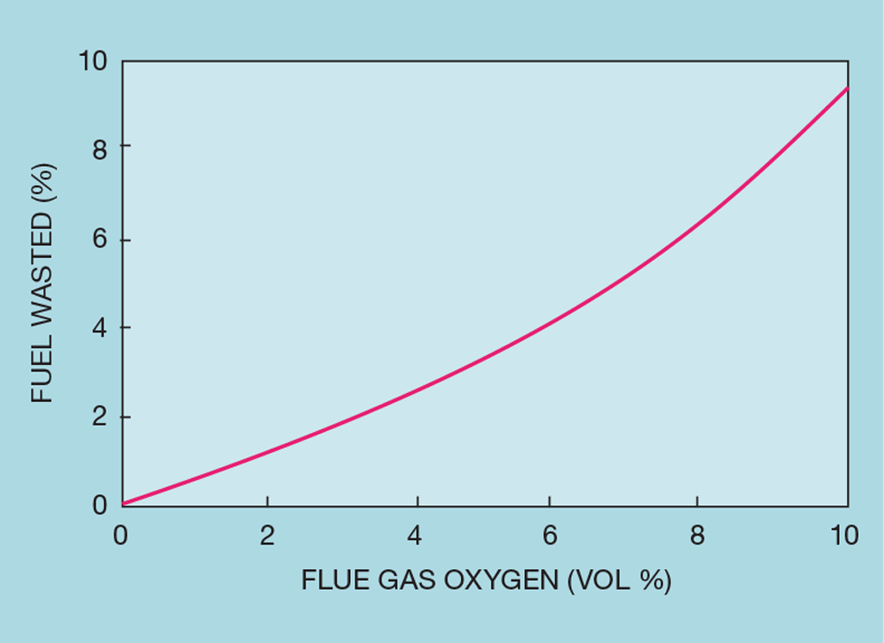
Figure 5 indicates the potential benefit. Under typical conditions, a 1% reduction in stack oxygen will reduce fuel consumption by 0.5 to 1%. However, the saving is highly dependent on the stack temperature. Often reduced by the installation of a combustion air preheater, recovering heat from the stack gas, the available saving can easily be halved.
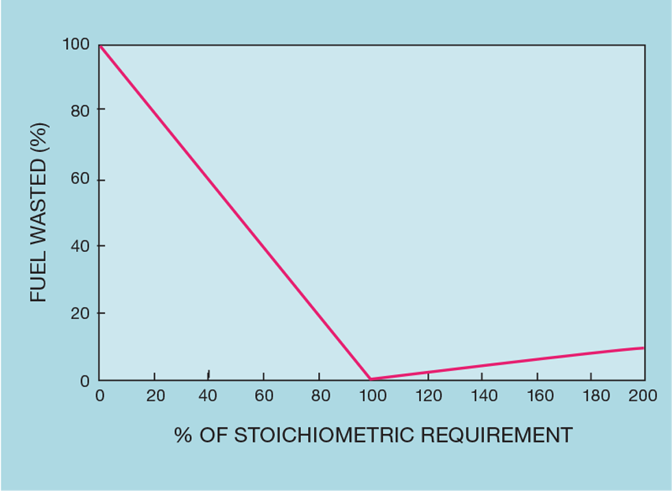
In principle, the control scheme maintains air flow in ratio to fuel flow, adjusting the ratio to meet the oxygen target. It is, however, important that this is implemented without increasing the number of occasions when combustion goes sub-stoichiometric. Apart from being hazardous, as Figure 6 shows, with no air preheater, the loss of unburnt fuel follows a slope ten times greater than that for the saving (20 times, if there is a preheater). One incident can wipe out the benefit achieved over several months. For this reason, control schemes nowadays are more than simple air-to-fuel ratios. One such scheme is properly known as cross-limiting. Its alternative name, lead-lag, is more descriptive. When fired duty is reduced, the change in fuel flow will lead the change in air flow but will lag behind the air on an increase. However, this name is ambiguous in that it also used for the unrelated lead-lag algorithm that we described in TCE 999.
Cross-limiting
Figure 7 shows one way of configuring the scheme. The stack oxygen control adjusts the air-to-fuel ratio (R); simultaneously it’s reciprocal, the fuel-to-air ratio is calculated. Imagine first that the temperature is above setpoint and so the controller reduces the heater duty. The signal is sent to both a low and a high signal selector. Because it is falling it will pass through the low selector and so reduce the fuel flow setpoint. The signal to the high selector will initially be blocked. However, as the fuel flow falls (as the green lines show) the competing signal will reduce and lets through that from the temperature control. It gets multiplied by the air-to-fuel ratio and so reduces the air flow in proportion. This makes the scheme safer. If, for any reason, the fuel does not reduce as required (maybe because the control valve has jammed) then the air flow will stay the same.

If the temperature controller requires an increase in duty, then this is initially blocked by the low selector and the fuel flow is unchanged. But the signal is allowed through the high selector, where it increases the air flow. The measured air flow is multiplied by the fuel-to-air ratio and (as shown by the red lines) represents the amount of fuel that can be completely combusted. As this rises, the low selector allows through the increase in fuel flow. If the air flow controller has failed, there will be no increase in fuel.
The scheme can introduce a controller tuning challenge. While the process is linear in the sense that the process gain is not affected, it is now non-linear dynamically. The air flow controller is likely to be considerably slower than the fuel flow controller. So, increases in duty will be slower than decreases. We must tune the temperature controller for the slower dynamics; otherwise, we risk excessive fuel flow overshoot when increasing duty.
Next issue
Split-ranging has long been a technique applied when we want to extend the rangeability of a controller – by having it manipulate more than one control valve. We’ll explain its history and its disadvantages – describing more effective alternatives.
The topics featured in this series are covered in greater detail in Myke King's book, Process Control – A Practical Approach, published by Wiley in 2016.
This is the eighteenth in a series that provides practical process control advice on how to bolster your processes. To read more, visit the series hub at https://www.thechemicalengineer.com/tags/practical-process-control/
Disclaimer: This article is provided for guidance alone. Expert engineering advice should be sought before application.
Recent Editions
Catch up on the latest news, views and jobs from The Chemical Engineer. Below are the four latest issues. View a wider selection of the archive from within the Magazine section of this site.


