Practical Process Control Part 11: Controlling Steam Drum Level
Myke King continues his detailed series on process control, seeking to inspire chemical engineers to exploit untapped opportunities for improvement
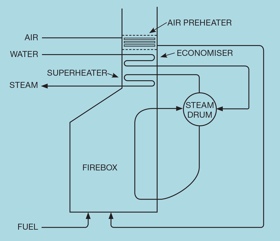
CONTROLLING the level in the steam drum shown in Figure 1 might at first appear a relatively simple scheme, manipulating the flow of boiler feed water to maintain the level at setpoint. However, two issues conspire to make it difficult.
The first is that we require tight, rather than averaging control. It is important that the level does not become excessively high and risk liquid entering the steam system. Similarly, it must not become too low and risk starving the boiler tubes of water. We therefore require a relatively large controller gain. The second issue is the change of phase from liquid to vapour. The drum contents do not behave as a simple liquid. This can require us to substantially reduce the controller gain below the desired value.
Shrink and swell
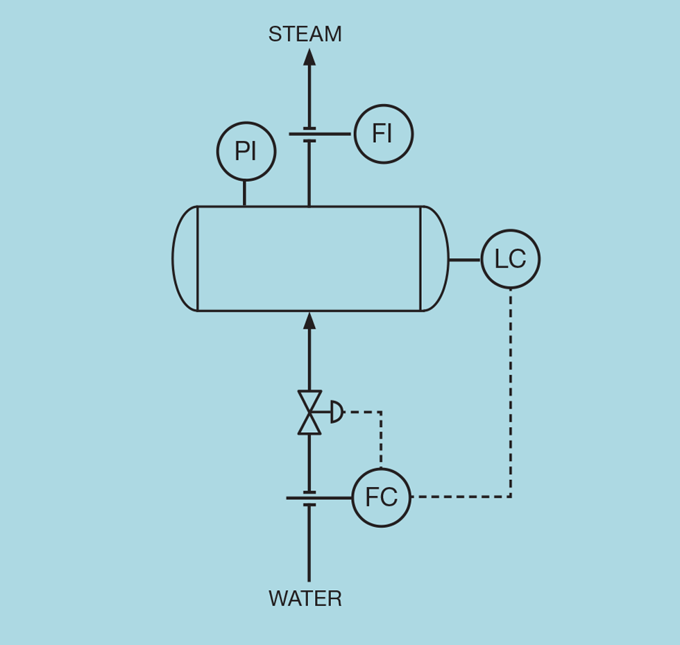
Figure 2 shows a conventional level controller. Consider what happens if there is a reduction in steam demand. Although the steam header pressure will be under control, there will be a transient increase in pressure before the pressure controller responds and reduces boiler firing. The material in the drum is not totally liquid but includes bubbles of water vapour. The transient increase in the drum pressure will compress these bubbles so that the water level falls. This is shrink (swell would be the result if the steam demand increases).
The level controller responds to shrink by increasing the flow of boiler feed water. However, falling steam demand requires less water; the level controller has initially made moves in the wrong direction. As the pressure reverts to setpoint, there will be surplus water in the drum that the level controller will then have to correct. If tightly tuned, the control response can become oscillatory. We must employ tuning closer to that used for averaging control, potentially risking excessive deviations from setpoint.
Level transmitter
Broadly, level transmitters operate by applying one of two principles. One is based on a float and so will directly measure level. The other uses two pressure transmitters placed one above the other to measure the pressure difference (the head of liquid). Installing this type is a potential solution. Head is a measure of mass, which is not subject to shrink or swell. It is the change in drum content density that causes the change in volume and hence liquid level. However, shrink and swell will also occur in the boiler tubes, displacing less or more liquid into the drum and so changing the mass of liquid it contains. Further, particularly on steam drums, engineering standards can demand that the true liquid level is measured rather than inferred from other measurements.
Signal conditioning offers a potential solution. Instead of the level controller using the measurement directly, we apply the correction
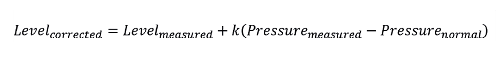
The term k is determined empirically. At steady conditions we switch level control to manual, then slightly change the drum pressure setpoint and note the change in level. Repeating this over a narrow range of pressures allows us to plot level against pressure. The slope of the resulting line is k. In principle, once implemented, the level measurement used by the controller will be almost immune to changes in pressure. However, this addresses only one of the potential problems.
Level transmitters operate by applying one of two principles. One is based on a float and so will directly measure level. The other uses two pressure transmitters
Inverse response
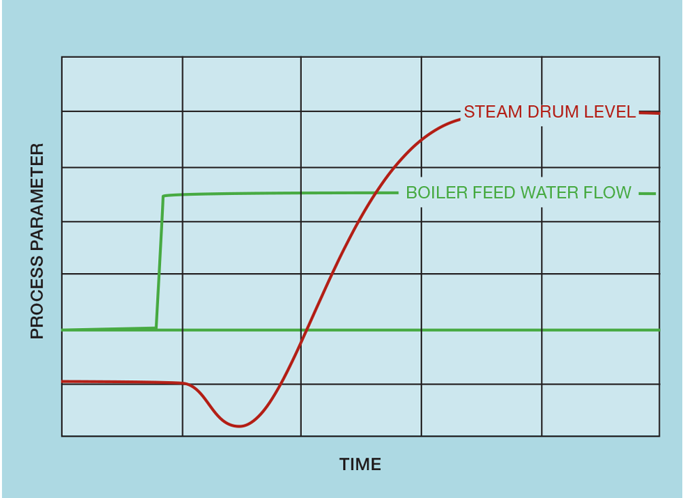
Inverse response is when the controlled variable responds to the manipulated variable by changing in the direction opposite to what we expect at steady state. In principle, the boiler feed water, passing through the economiser, has recovered heat from the flue gas to reach the bubble point of the water in the drum. In practice, it will be somewhat cooler. So, if we imagine that the level is below setpoint, the controller will increase the flow of water. On entering the drum this will cause a small reduction in drum temperature and so less of the contents will be converted to steam and the volume of entrained vapour will reduce. This causes the water level to fall – the opposite of what we expect on increasing the flow of water. Figure 3 illustrates this behaviour when the flow of water is changed manually. If the level controller were in automatic mode, it would respond by making a further increase in flow, which initially causes a further reduction in level. If tightly tuned, the controller would almost certainly be unstable – again requiring tuning to be more akin to averaging control.
Noise
The level measurement is prone to noise. The boiling water will have a turbulent surface. A well-engineered installation might include baffles or a stilling well but is unlikely to be sufficient to completely eliminate noise. To avoid control valve damage, we are likely to have to compromise on the requirement for a large controller gain. We will address filtering, as a means of noise reduction, in the next article. However, filtering level measurements is generally counter-productive, particularly when tight control is required. It introduces a lag into a process which has virtually none – so requiring a substantial change in controller tuning.
Three-element level control
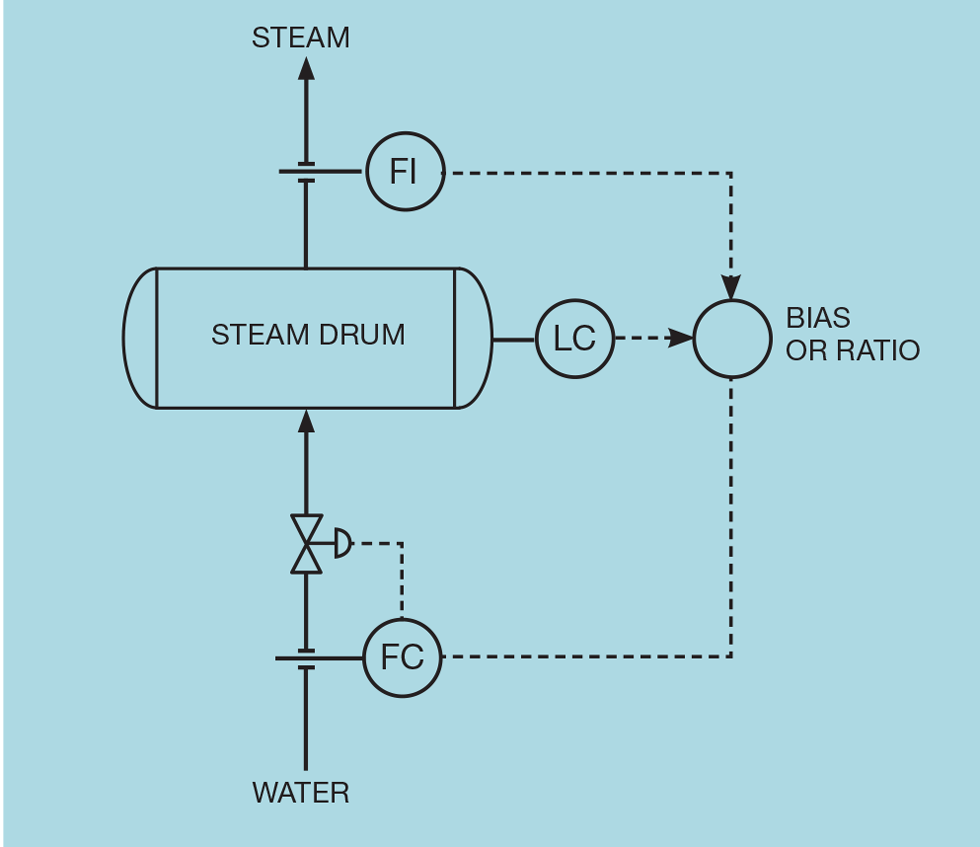
Figure 4 shows the scheme designed to deal with the problems of shrink/swell, inverse response, and noise. It is a very early example of feedforward/feedback control. By measuring the steam demand, we can keep the flow of water equal to the demand and so, in theory, the water level will not change. This is the feedforward part of the scheme. The level controller relies on feedback to correct any deviation from setpoint or, indeed, permit the operator to change the setpoint.
Most of the corrective action is taken by feedforward control. This does not stop shrink/swell or inverse response, but the flow of water is now changed in the correct direction. The level controller needs now only take trim action correcting for minor deviations caused, for example, by flow metering errors. Much slower tuning can be implemented, so avoiding any oscillatory behaviour. And, with a much lower controller gain, measurement noise is unlikely to cause a problem.
Conventionally the scheme is configured using a bias algorithm. The level controller adds (positive or negative) corrective action to the measured steam demand. An alternative scheme employs a ratio algorithm. This maintains the water flow in proportion to the steam flow, with the level controller trimming the proportion as necessary.
The bias scheme was first implemented some 80 years ago when only pneumatic instrumentation existed. Summing pneumatic pressures is readily achievable; multiplying them is not. However, the disadvantage of the bias scheme is that the flowmeters must be calibrated in consistent units. In most of the world this is already likely to be the case. Steam demand is likely measured in metric tonnes (per hour) and water flow in cubic metres (per hour). The density of water is very conveniently 1 t/m3. However, in the US, water is likely to be measured in US gallons (USG/hr) and steam in pounds (lb/hr). The bias algorithm in modern control systems supports the inclusion of a scaling factor. In this example that factor would be applied to the steam flow – multiplying it by the reciprocal of water density (0.12 USG/lb).
The use of ratio feedforward would appear to offer that advantage in that it will work whatever the units. Only the target changes. In metric units it would be 1. In imperial units it would be 0.12. However, its use does have a disadvantage often mentioned in the literature. We know that, at constant steam demand, the rate of change of level is proportional to the water flow

But the water flow is set by the ratio target (R) and the flow of steam

The level is the process variable (PV) of the controller. It manipulates R, which is thus its manipulated variable (MV). In general, for an integrating process

Comparing equations shows that the process gain (Kp) varies

Boilers can have a 4:1 turndown ratio and so Kp could potentially change by a factor of four. In theory this could cause a tuning problem. However, since the level controller is providing only a trim action, it is likely that it can be tuned to be robust over the whole operating range.
Next issue
Our next article will cover filtering as an example of signal conditioning. Filtering may be required to prevent measurement noise being transmitted to, and potentially damaging, the control valve. We’ll explain the standard filter available in each of the leading distributed control systems (DCS). And we’ll show how a custom filter enables derivative action to be used without excessively amplifying the noise.
The topics featured in this series are covered in greater detail in Myke King's book, Process Control – A Practical Approach, published by Wiley in 2016.
This is the eleventh in a series that provides practical process control advice on how to bolster your processes. To read more, visit the series hub at https://www.thechemicalengineer.com/tags/practical-process-control/
Disclaimer: This article is provided for guidance alone. Expert engineering advice should be sought before application.
Recent Editions
Catch up on the latest news, views and jobs from The Chemical Engineer. Below are the four latest issues. View a wider selection of the archive from within the Magazine section of this site.


