Getting Started Part 1: Shell and Tube Heat Exchangers
In this new series, Everard Brewester focuses on the process equipment that form the building blocks of process plants
HEATING and cooling of process streams is an integral part of every process, and these duties are carried out in heat exchangers. They are also used to transfer heat between the streams, improving the thermal efficiency of the process.
How do they work?
Shell and tube exchangers consist of tubes, the ends of which are secured in tubeplates, all contained within a cylindrical shell.
In designing an exchanger, care must be taken to:
- ensure that adequate convective coefficients are obtained on each side of the tube wall, by keeping velocities up, within the limitations imposed by pressure drop
- allow for differential thermal expansion between the tubes and the shell
- account for the formation of fouling films on both sides of the tube wall, which reduce the overall heat transfer coefficient between tube-side and shell-side fluids, and which may need occasional removal by cleaning
Tubes, usually of 3/4 inch or 1 inch outer diameter (OD), are arranged on a triangular, square, or rotated-square pitch. Triangular pitch is the most economical, as shell diameter is minimised and a good heat transfer coefficient is obtained. Square pitch can be cleaned on the shell side by pressure-jetting more easily, and rotated-square pitch retains ease of cleaning while giving better coefficients.
Although 20 ft (6.1 m) is often said to be the “standard” tube length, the Tubular Exchanger Manufacturers Association (TEMA) quotes lengths down to 8 ft (2.4 m). Depending on the capabilities of the fabricator and the plant’s maintenance facilities, lengths of up to 40 ft (12 m) can be considered.
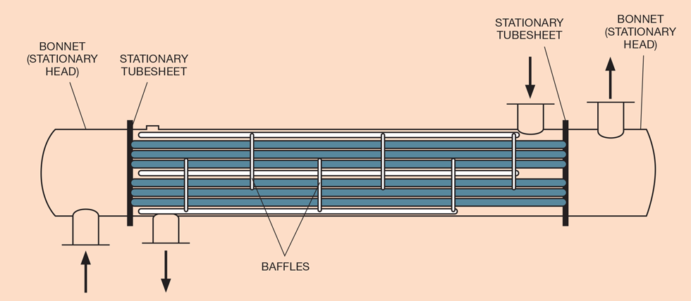
The simplest exchanger type is the fixed tubeplate, shown in Figure 1, in which flows on the tube and shell side are counter-current to each other. Vertical baffles are placed around the tubes on the shell side to increase fluid velocity and hence the shell-side coefficient. Velocity and pressure drop can be adjusted by varying the separation of the baffles. Differential expansion in this design is accommodated either by limiting the shell to tube-side temperature difference or by fitting an expansion bellows to the shell.
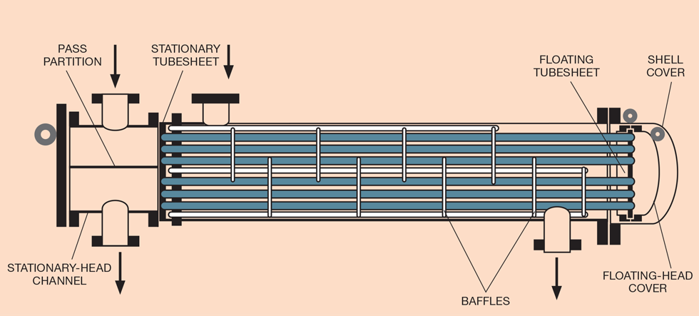
Another widely used type is the floating head exchanger, which is better in fouling duties (see Figure 2). In this design, a cover is placed over the “far” tubeplate, which is allowed to move inside the shell to accommodate tube movement. A partition plate is placed in the “near” channel and so there are two passes on the tube side, doubling fluid velocity.
Up to eight tube passes may be made, provided pressure-drop limits are not exceeded. This arrangement is not so clearly counter-current, as the tube-side fluid moves in different directions.
There are a number of designs for the floating head, one of which allows the tube bundle to be removed from the shell more easily, the so-called “pull-through” type.
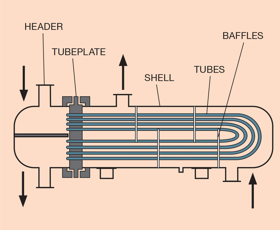
U-tube exchangers (see Figure 3) have only one tube plate and so there is no problem with differential expansion. This design is particularly useful when the tube side is at high pressure. U-tube exchangers with enlarged shells form kettle reboilers.
The ability of the different designs to be mechanically cleaned is summarised in the table below:

Where mechanical cleaning is impossible, it might be possible to use chemical cleaning.
Inability to clean one side of an exchanger means only clean fluid should be placed there.
The maximum tube area that can be accommodated in a single shell can be gauged from an exchanger using 3/4 OD tubes, 9 m long, in a shell of 1.5 m diameter having a tube surface area of 1,580 m2.
For a given tube area, there is little difference between the costs of the three exchanger designs. U-tube kettle reboilers are significantly costlier because of their enlarged shells.
Which fluid where?
Choosing which fluid to put on the shell or tube side is an important decision. It may be eased by consulting the following table with reasons for putting a fluid on the tube side:
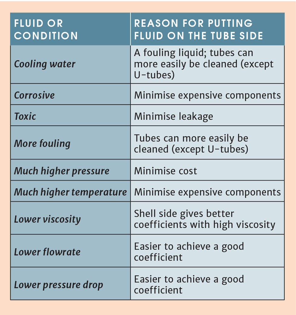
Total condensation is usually carried out on the shell side.
Unfortunately, there will be cases where these allocations will be contradictory, such as cooling a high-pressure fluid against cooling water. There is no simple answer to this.
Setting temperatures
Heat transfer is driven by the temperature difference between the hot and cold streams. The temperature difference varies along the length of the tubes and so the log mean temperature difference (LMTD) is used as a measure of the effective temperature difference over an exchanger.
For the exchange duty shown in Figure 4 on a heat release versus temperature plot, LMTD is defined for purely counter- or co-current flow, by the greater terminal temperature difference and the lesser terminal temperature difference, where:
LMTD = (GTTD - LTTD)/ln (GTTD/LTTD)
In this case:
LMTD = (40 - 20)/ln (40/20) = 28.8°C
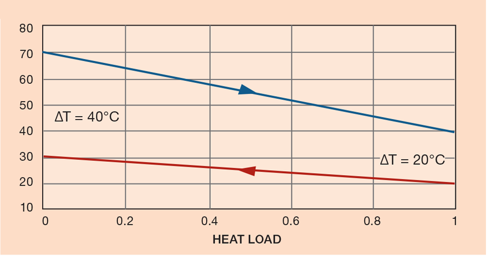
The temperature difference at the cold end of the exchanger is called the approach, in this case 20°C. Exchangers with multiple passes on the tube or shell side do not have purely counter-current flow, because the direction of each stream changes with every pass.
The calculated LMTD in these cases is reduced by using the correction factor F, which is based on the inlet and outlet temperatures for both fluids and how the flow is arranged. Charts showing values of F are available online. It is widely advised that exchanger arrangements having a value of F less than 0.75 should not be used, although 0.85 would be even better.
Temperature approach
The temperature of a stream entering and leaving an exchanger must be fixed to calculate the heat load. The terminal temperatures of the other stream must be fixed before the exchanger can be designed.
Cooler
The supply and return temperatures of cooling water will usually be fixed across a site. These temperatures determine the temperature to which the process can be cooled (see Figure 5). In this exchanger, the temperature approach has been fixed at 35 - 25 = 10°C , which is widely used. For exchangers using refrigerants (and the attendant cost of compression), the approach may be reduced to 5°C and in cryogenic exchangers to as low as 1 to 2°C.
If an exchanger is likely to have a poor overall heat transfer coefficient it would be reasonable to use a larger approach, although this is difficult to quantify. Similarly, a wider approach may be justified with expensive exchangers, such as those at high pressure or being constructed in expensive materials.
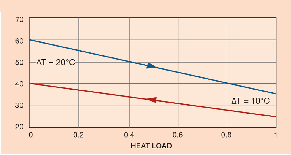
Please observe that, in this exchanger, the heated outlet temperature (40°C) is higher than the cooled outlet temperature (35°C). This is called a temperature cross and is unpopular with exchanger designers because the LMTD is degraded so much. In this example the correction factor is F = 0.6. The situation can be improved by increasing the cold fluid’s flow, thus reducing its outlet temperature. This can be done until the cold outlet temperature is equal to the hot outlet temperature (ie cross = 0°C). If you are proposing to use a small temperature cross, check the value of F from the correction factor chart.
The problem with crosses can be solved by arranging for more than one pass on the shell side, by using a horizontal baffle in the shell. This is mechanically less practicable, and an even better solution would be to split the duty between two exchangers in series, which is obviously more expensive.
Phase change
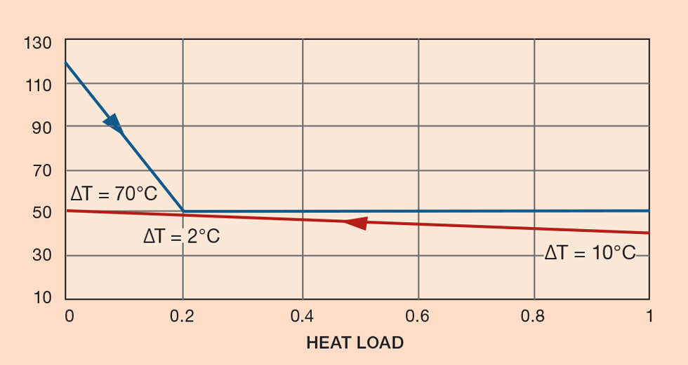
The cooling curve in a condenser is quite different (see Figure 6). The steeply sloped portion is where the gas is being cooled, the flat portion for condensation. Depending on the relative sizes of the cooling and condensing loads, a temperature pinch can be created (2°C in this case), which can be zero or even negative. Once again, increasing the coolant flow rate and so reducing its outlet temperature will increase the size of the pinch, so reducing exchanger size. Alternatively, the condensation temperature could be raised.
Interchanger
Figure 7 shows the heat load versus temperature profile of an interchanger in which heat is exchanged between hot and cold streams. A typical example of this is an exchanger preheating a column’s feed, while cooling the bottoms product. T1 and T2 are not yet fixed. By reducing T1, the size and coolant consumption of a following cooler will be reduced. By increasing T2, the heat load on the column’s reboiler will be reduced.
If a temperature cross is to be avoided, T1 can be set equal to T2. If the flow rate of the bottoms is 70% of the column’s feed:
0.7 (120 - T1) = T2 - 40 = T1 - 40
Therefore:
T1 = T2 = 72.9°C
If the temperature cross is neglected, by use of a multi-pass shell or a number of exchangers in series, T1 can be set at 50°C (a 10°C approach) and so T2 = 89°C and the amount of heat recovered increases by 49%.
Allowing for fouling
Experience has shown that the inner and outer tube surfaces become fouled owing to the accretion of solids through precipitation, crystallisation, biological growth, and other mechanisms. The incidence of fouling increases at low-fluid velocities and at higher temperatures.
Fouling can significantly reduce the overall heat transfer coefficient between shell-side and tube-side fluids and increase pressure drop. The expected degree of fouling is allowed for in the design of exchangers by the inclusion of fouling resistances in the calculation of overall coefficient:
I/U = 1/h1 + 1/h2 + R1 + R2
Where U is the overall coefficient, h1 and h2 are the convective coefficients inside and outside of the tube wall and R1 and R2 are fouling resistances. Inclusion of such resistances can reduce the overall coefficient by as much as 50% when h1 and h2 are large.
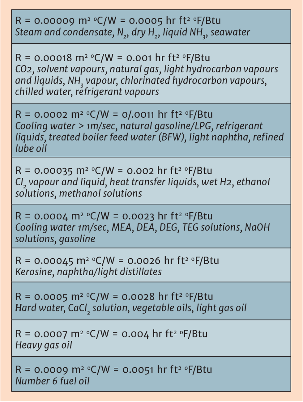
In the table below, the value of fouling resistances from several sources are related to the nature of the fluids giving rise to them. In this way it should be possible to assign a resistance to your fluids by seeing which fluids in the table they most resemble.
Setting allowable pressure drop
Fluid pressure drop (DelP) in an exchanger is related to convective coefficients because the turbulence that leads to such coefficients also creates pressure drop. The relationship is approximately:
U = const x DelP^ 0.33
Setting pressure drops is therefore a significant step in specifying an exchanger. An unnecessarily low DelP will lead to a large exchanger and a high DelP will increase pumping or compression costs.
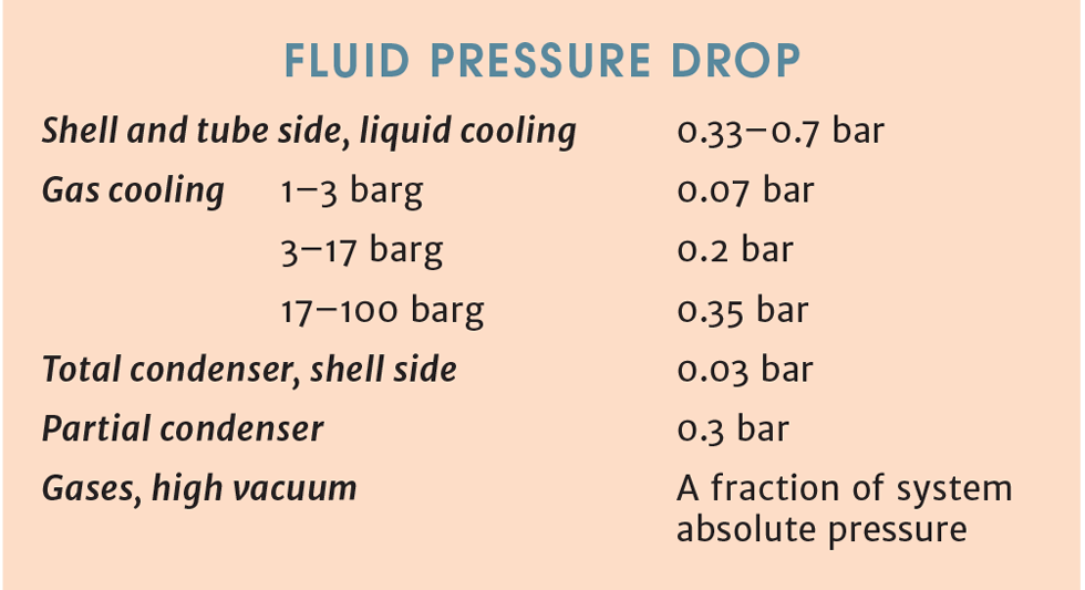
There may be an optimum DelP for every situation, but there is rarely time to discover this. DelP is usually based on prior experience, and some examples are given below:
Heat exchanger sizing
It is sometimes necessary to make a preliminary estimate of exchanger size (ie heat transfer area) as the basis for a cost estimate.
The most usual approach is to assume an overall coefficient (U) and use the equation:
Area = Q/U (delta T)
This is problematical because published values of U cover so many possible combinations of the variables involved, such as the fluids on each side, whether condensation occurs, and what allowance has been made for fouling.
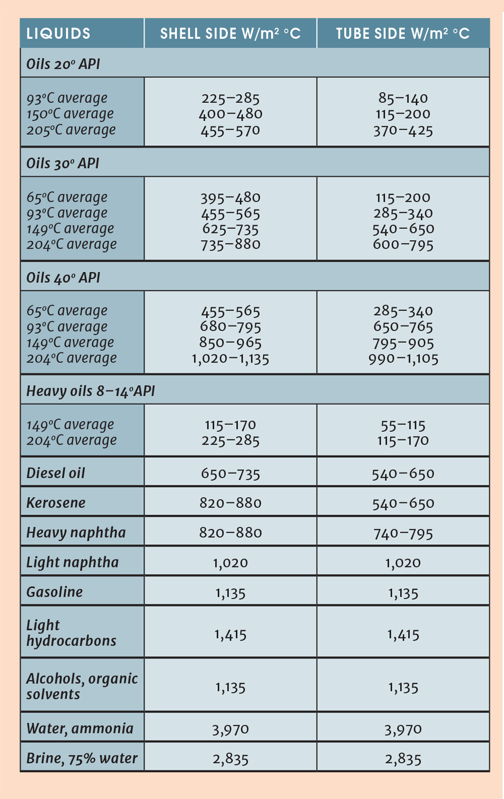
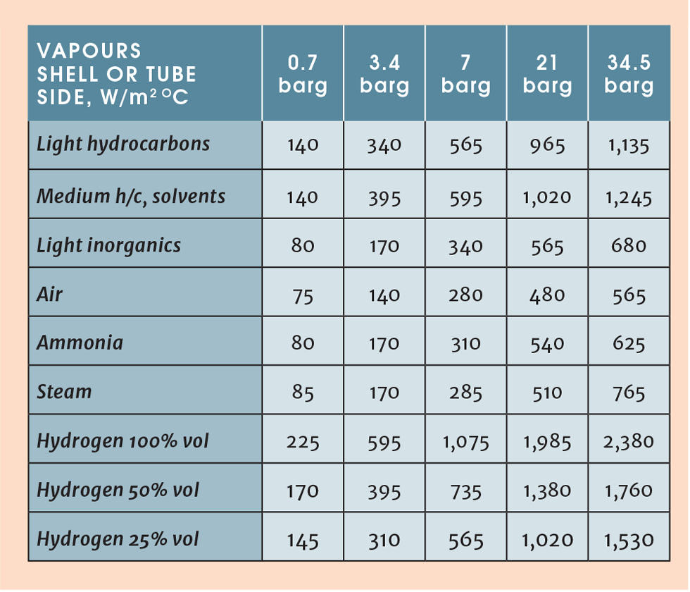
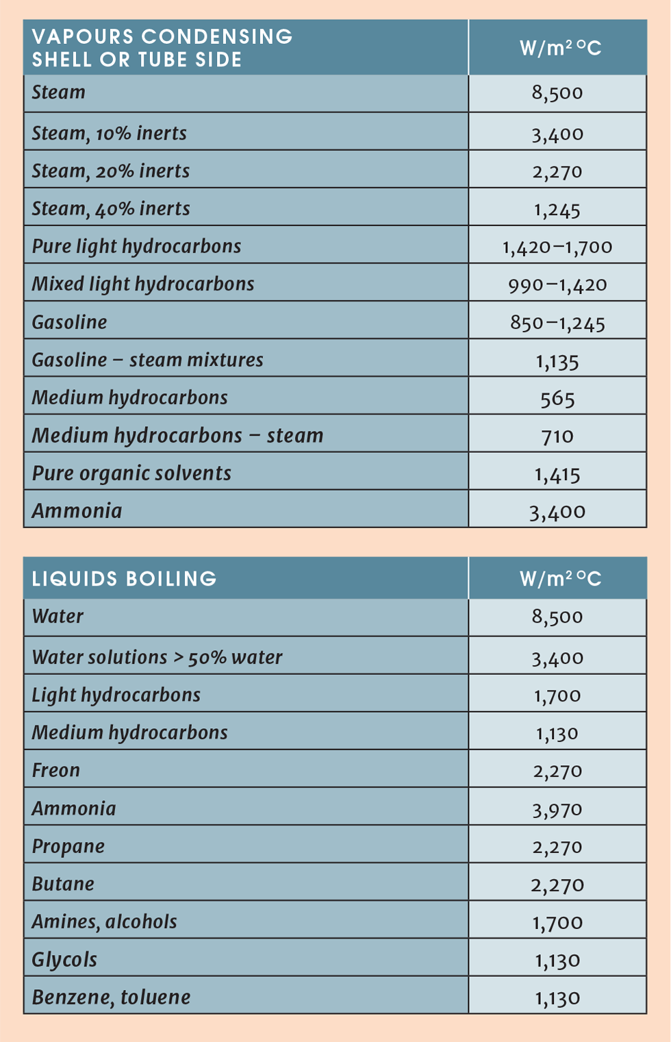
An alternative, proposed here, is to build up U from the convective coefficients and fouling factors on shell and tube side. Typical fouling factors were given in the section on fouling and the individual coefficients can be taken from the table below (note that 100 BTU/hr ft2 °F = 567 W/m2 °C)1
Worked example
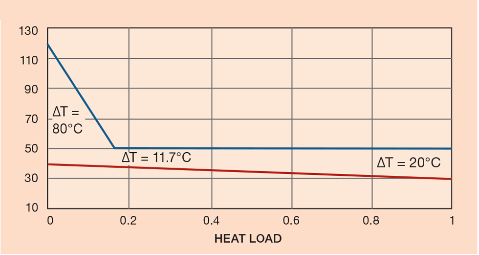
A plot of temperature versus heat release for an ammonia condenser is shown in Figure 8, with cooling water on the tube side. The exchanger works at 19.7 barg on the process side:
Delta H cooling = 213.3 kJ/kg (from 120 to 50°C)
Delta H condensing = 1,044.6 kJ/kg (at 50°C)
Total delta H = 1,257.9 kJ/kg
Water temperature at the pinch = 30 + 1,044.6 x 10/1,257.9 = 38.3°C
Ammonia flow = 50,000kg/hr
Cooling zone
Cooling load = 50,000 (213.3) = 10,665,000 kJ/hr = 2,962 kW
h NH3 = 540 W/m2 °C
h C W = 3,970 W/m2 °C
R NH3 =0.00018 m2 °C/W (from section on fouling)
R C.W = 0.0002 m2 °C/W
1/U = 1/540 + 1/3,970 + 0.0002 + 0.00018 = 0.0025
U = 402 W/m2 °C
LMTD = (80 - 11.7)/ln (80/11.7) = 35.5°C
Therefore, area = 2,962 x 1,000/35.5 x 402 = 207 m2
Condensing zone
Condensing load = 50,000 (1,044.6) = 52,230,000 kJ/hr = 14,508 kW
1/U= 1/3,400 + 1/3,970 + 0.00009 + 0.0002 = 1,200 w/m2 °C
LMTD = 15.5°C
Therefore, area = 14,508 x 1,000/1,200 x 15.5 = 780 m2
And, total area = 207 m2 + 780 m2 = 987 m2
Reboilers
Column reboilers are a specialised but widespread use of heat exchangers. Other than forced circulation reboilers (which are no different from other exchangers), the types used are horizontal and vertical thermosyphons (where there is only partial vaporisation per pass on the process side) and kettle reboilers where there is complete vaporisation. There are pros and cons for all types.
In kettle reboilers, the shell-side pressure drop is negligible and does not affect the exchanger’s hydraulic performance. To avoid film boiling on the tubes, which limits heat transfer rates and can lead to rapid fouling, heat flux through the tubes is limited to 9,000 Btu/Hr ft2 (28,370 W/m2) which also limits the temperature of the heating medium. With the high boiling coefficient achieved with these exchangers, the temperature difference between process and steam will probably be limited to less than 30°C.
In the vertical or horizontal thermosyphon designs, circulation is driven by the head difference between the inlet liquid and the two-phase mixture returning to the column. The net head provided must be balanced against the pressure drop of the exchanger and its associated pipework. To provide a safety margin, it has been suggested that the calculated net head should be twice the exchanger plus pipework resistance.
Maximum flux in thermosyphons is 15,000 Btu/Hr ft2 (47,280 W/m2), which allows temperature differences of about 50°C. The amount of vaporisation can be between 5 and 50%. As a starting point for specifying a thermosyphon, take the vaporisation per pass to be 30% and the process-side pressure drop to be 0.035 bar.
Specifying the exchanger
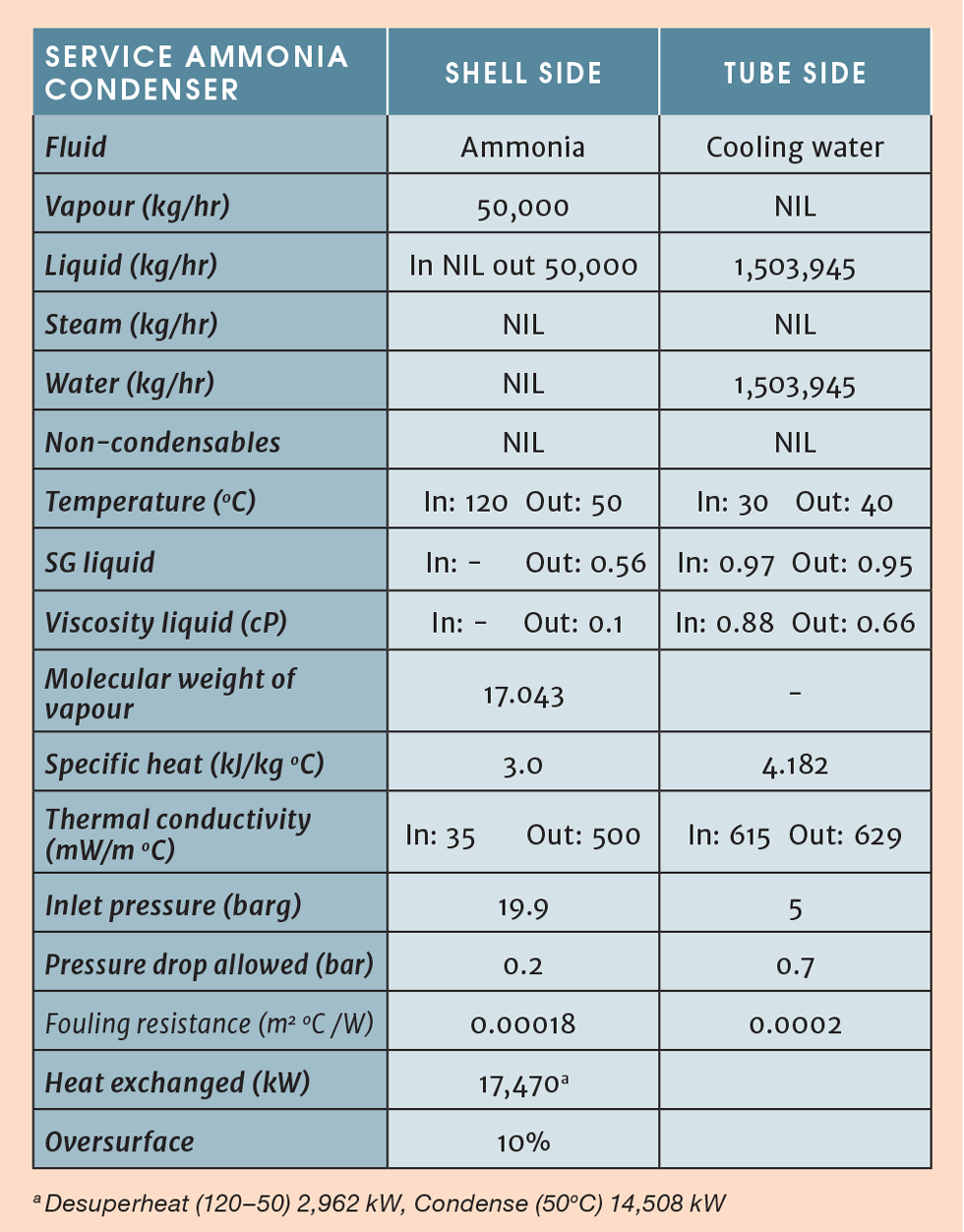
Provide all the information needed by the exchanger designer (see Table 7). The pressure drop allowed on the shell side is to cover the desuperheating zone, while the exchanger is to be oversized by 10% as a safety margin.
Checking and authorisation
Finally, get your calculations and specification checked and authorised by a more senior engineer, who is authorised to do so.
Reference
1. Data originally from Yuba Heat Transfer Corp
This is the first in a series on the process equipment that forms the building blocks of process plants. To read more, visit the series hub at https://www.thechemicalengineer.com/tags/getting-started-series
Disclaimer: This article is provided for guidance alone. Expert engineering advice should be sought before application.
Recent Editions
Catch up on the latest news, views and jobs from The Chemical Engineer. Below are the four latest issues. View a wider selection of the archive from within the Magazine section of this site.


