Screening Heat Exchangers for High Pressure Differential Relief
This article will provide an insight into the Energy Institute’s guidance on pressure relief in shell and tube heat exchangers with high differential pressures. In addition, this article will summarise the key decisions and calculation methods advised by the Energy Institute for the safe operation of heat exchangers in order to tolerate the impact of tube failure.
Introduction
In 2015 the Energy Institute (EI) published the second edition of Guidelines for the Safe Design and Operation of Shell and Tube Heat Exchangers (STHE) to Withstand the Impact of Tube Failure1. The report covers the stages of new STHE design, pressure relief system design, instrumentation and relief device selection as well as the reassessment of existing heat exchangers.
One of the most common forms of heat transfer across the process industries is a shell and tube heat exchanger. The focus of this article will be in the case of a high pressure (HP) gas within the tube side and a low pressure (LP) liquid in the shell. Since the two sections of the heat exchanger operate at high differential pressures, the risk of a leak from the HP to LP side is ever present. Engineering best practice dictates that the LP side is designed for the blocked-in pressure of the process fluid. However, it is rarely designed to be capable of withstanding the operating pressure of the HP side. The LP side must therefore be protected against a tube leak or rupture since this could result in a loss of containment with potential safety, environmental and/or financial consequences.
Currently, overpressure protection is usually provided by a rupture disc(s), with relief valves installed in some circumstances. Whilst there are numerous causes of overpressure in STHEs, all of which should be considered, this article focuses on the tube failure scenario. Surge pressure, in particular, will be considered for the tube failure scenario when designing overpressure protection from the high pressure side.
STHE design
When designing a STHE, the relative pressures should be considered with the knowledge that a relief system must be designed for tube rupture (in addition to other potential overpressure cases).
When the heat exchanger tube contains high pressure gas and is in a liquid-filled shell (eg gas coolers in cooling water systems), the problem is greater than with gas-gas and non-flashing liquid-liquid exchangers. If the tube rupture occurred suddenly then the relief device would have to pass liquid at a volumetric rate equal to the gas rate flowing from the ruptured tube (ie "plug-flow" condition). This can result in a pressure rise that could be very sudden, causing a shock wave to occur. A relief device would have to act very rapidly to avoid local overpressuring of the shell. This situation is worsened when the tube contains liquid which flashes after escaping from the ruptured tube since this can generate an even larger flow of gas; (eg, such a situation could arise with exchangers handling water and hot oil, or with superheated water in the tubes).
After a rupture occurs, the initial step change in pressure will distribute away from the rupture site in all directions. The surge of increased pressure will travel at the wave speed in the liquid and is equal to Pr + ΔPis.
Pis is the gas impact induced initial step pressure (Pa) and Pr is the operating pressure of the low pressure liquid (Pa).
As the wave travels through the heat exchanger, the initial surge in pressure is increased further due to the reflection of the wave causing an additive effect. This can occur when the wave encounters a geometry change such as a bend in pipework, exchanger endplate, or an additional relief valve. At the point of wave reflection there is an increase in amplitude of ΔPis. For this reason it is advised that, if possible, the LP side of the exchanger should be designed to be able to accommodate a pressure of Pr + 2ΔPis. However, it should also be noted the pressure surge can be greater than this with multiple reflections.
The EI guidance states that in simple heat exchangers, protected by spring-loaded and buckling pin relief valves, the reflection surge pressure was found to be up to two times the pressure of the incident pulse. This phenomenon can occur when the initial pulse is insufficient to open the relief valve fully and reflection occurs off the valve seat. It was determined that in rupture discs this effect is insignificant since the pulse duration will be very short due to fast opening times.
Determination of the required relief device therefore must consider the extent of overpressure caused by the HP side, pressure wave reflections, and the device response time. These considerations will ultimately enable the chosen relief device to limit the pressure to within the maximum allowable accumulated pressure.
To that end, the EI completed extensive testing on opening times of relief devices. The results of this testing are summarised in Table 1 which displays the suggested opening times of relief devices, including a safety factor.

It was found that the shorter the opening time of the selected relief device, the greater the reduction of the peak pressures within the exchanger especially in smaller heat exchangers.
Consequently, the following relief device selection criteria were devised:
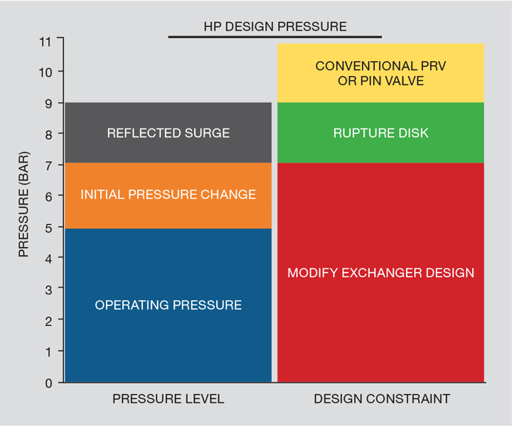
If: Operation pressure + 2x initial pressure change <LP corrected hydrotest pressure
then: Conventional pressure relief valve/pin valves are acceptable.
If: Operation pressure + initial pressure change <LP corrected hydrotest pressure
then: Rupture discs must be installed.
If: Operation pressure + 2x initial pressure change >LP corrected hydrotest pressure
then: Modification of heat exchanger design is required.
An example of this can be seen in Figure 1. It shows an exchanger with LP operating pressure of 5 bar and a HP design pressure of 11 bar. In this case the initial surge pressure is found to be 2 bar. It can therefore be seen that if the LP test pressure is less than 7 bar the exchanger must be modified. From 7–9 bar a rupture disk is required and from 9–11 a conventional PRV would suffice.
Calculation methodology
A STHE tube rupture presents itself in two ways. The first is a small ‘pinhole’ leak leading to contamination of the LP fluid for which overpressure protection is required.
The second is a catastrophic tube rupture. When calculating the required relief rate, it is advised that the methodology in American Petroleum Institute Std 521 – Pressure-Relieving and Depressuring Systems2 is followed, as was done after previous publications by the EI. For example, assuming the rupture flow path to have an area equal to twice that of one tube end is still considered best practice.
The area in which the recent EI guidance gives some pertinent variation to API Std 521 is in the calculation of surge pressures following a tube rupture.
At the point of tube rupture, a surge in pressure is created by the impact of the gas entering the shell (gas impact induced initial step in pressure). This will travel through the exchanger at wave speed. As stated above, this wave can be reflected and amplified after meeting a surface such as a relief valve seat or exchanger internal wall (ie, the limits of the heat exchanger) which will often lead to the highest pressures reached in a relief event. Whilst this surge pressure is often calculated using dynamic modelling, EI has suggested a method for estimating the surge.
Surge pressure estimation
When selecting the required relief device, the key factors are the design pressures of HP and LP sides of the exchanger, operating pressures and the surge pressure. A higher surge typically requires a faster response from the relief device.
In order to calculate the initial surge pressure (Pis) before any reflection effects, Equation 1 is given:

The EI guidance states that the coefficient of discharge for the tube is assumed to be in the region of 0.6–0.975. Where 0.6 is representative of the initial break with the gas from a tube rupture entering a liquid. As the gas bubble caused by the tube rupture expands, the discharge coefficient will move to 0.975 as there is less resistance than when liquid is present at the rupture site. For those who have sized relief valves previously, it can be seen that the discharge coefficient is comparable to a relief valve and as such, should be treated with similar caution when selecting the figure to enter. It is recommended that the sensitivity of the design to the discharge coefficient is checked in order to ensure a conservative approach.
Certain geometries, such as very long exchangers with close baffle spacing, can result in more than one positive pressure reflection and complex dynamics. In such cases, dynamic simulation is recommended. However, for many cases (such as simple geometries where the pressure wave is reflected only once) the estimation above can be used to show the suitability of a relief device or the requirement for an exchanger that is being designed, meaning further detailed analysis and validation are not required.
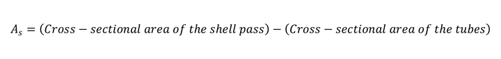
Estimation of characteristic shell area (As)
Characteristic shell area, As, is the effective cross-sectional area of the liquid in the path of the gas bubble and therefore is unique to a particular heat exchanger. It is required in equation 1 presented above and can be calculated using equations 2 and 3.
Good engineering judgement should be used in selecting a suitable characteristic shell area; using too large a characteristic shell area can result in underestimating the surge pressures due to tube rupture. Dynamic simulation is recommended for complex geometries.
Equation 2, for longitudinal baffled heat exchangers:
Equation 3, for transverse baffled heat exchangers:

Effective length of the shell pass refers to the actual distance the pressure wave travels, from the tube rupture around each baffle. Figure 2 shows both longitudinal and transverse baffles. Example calculations can be found within the EI guidance.

Conclusions
In conclusion there are many aspects to consider in designing overpressure protection for shell and tube heat exchangers. It is imperative that all potential overpressure cases are identified and the required relief rate calculated, based on methods such as those laid out in API Std 521.
Tube ruptures causing HP gas to enter the LP liquid in the shell are frequently determined as the governing pressure relief scenario in shell and tube heat exchangers. The highest pressure within the LP side is often found to be in the initial transient phase caused by an impact-induced initial step or surge that is reflected off geometrical changes. The pressure increase is often calculated using dynamic simulations showing the surge changes with time. This can be costly and time consuming. The EI has therefore presented a method of estimating the maximum surge pressure which can be used in simple design work.
The method allows the assessment of the maximum pressure in the LP side and therefore the required relief device.
However, engineering judgement must be used in order to assess the most applicable method in each case, since complex geometries or very large exchangers may still require further analysis
References
- Guidelines for the Safe Design and Operation of Shell and Tube Heat Exchangers to Withstand the Impact of Tube Failure, 2nd Edition, November 2015, Energy Institute.
- American Petroleum Institute Std 521 – Pressure-Relieving and Depressuring Systems.

Recent Editions
Catch up on the latest news, views and jobs from The Chemical Engineer. Below are the four latest issues. View a wider selection of the archive from within the Magazine section of this site.


