Pulse Sensors for Flow Measurement Devices and Applications
Neil Hannay explains how to understand flow meter sensor and pulse output types for efficient system operation
FLOW meters have developed into many forms over the years, from mechanical devices – such as a turbine or rotating gear – which rely on measuring the movement of a rotational component, to devices that use ultrasound, and other advanced technologies. These meters generally use a sensor to relay flow measurements to a reading device. Nearly all types of flowmeters, from ultrasonic to turbines, are offered with pulse output flow signals. Sensing components used in a flowmeter measure the movement or flow rate of the liquid or gas passing through the system. The pulse output signal from these devices is, in essence, an on/off switch which changes state at a frequency related to the fluid flow.
This technical review aims to go “back to basics”, providing a foundation understanding of typical output pulse types for flowmeters and drawing on examples of their application, illustrating which output sensor works best in different environments. This will help readers to make an informed decision when selecting the optimum output pulse type for their flow meter and the process application that it is operating within.
The input circuitries of flow indicators often have configuration routines to accommodate the device’s output. Pulse output sensors need to be connected to a suitable pulse counting read-out device and correctly configuring these connections is crucial for proper system operation. Such read-out devices have typically been a dedicated display, a programmable logic controller (PLC), or LabVIEW directly interfacing on a PC. We now also see increasingly popular options like Arduino and Raspberry Pi.
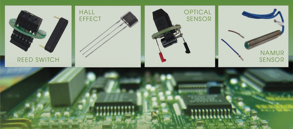
We will review different pulse outputs and sensors and discuss where they are advantageous, along with the best practices for connecting them to the desired read-out device.
Reed switch
The reed switch represents the simplest form of pulse output. It is merely a magnetically operated mechanical device composed of two ferromagnetic reeds sealed within a glass envelope. They are typically inexpensive and easy to understand but are limited to lower frequencies. Reed switches can be used in hazardous areas provided there is no risk of extraneous voltages or currents being produced. In this environment, simple apparatus design can be suitable for safe operation as there is no possibility of these extraneous voltages or currents in a correctly designed circuit.

Reed switches are a desirable alternative to other sensors for applications where energy efficiency and low power consumption are essential. This is due to the mechanical design of the sensor that gives zero energy consumption while the switch is in a passive state. The reed switch essentially functions by switching the voltage offered to it, and if appropriately protected, this form of pulse output is perfect. The logging flow meter detects the voltage change when the switch closes. However, there are a few limitations to consider.
As reed switches are mechanical devices, they have a finite lifespan, with fatigue and breakage likely after around 109 operations under ideal conditions. The contacts should be protected by a current-limiting component to prevent a voltage supply being directly switched, causing them to weld together. In hazardous atmospheres, this extra protection may prevent an intrinsically safe instrument from reading the contact closures and so should be removed.

Another potential issue is a phenomenon called “contact bounce” exhibited in reed switches. This refers to the rapid opening and closing of the switch contacts which can be erroneously detected by the electronics as valid pulses.
Two solutions are available to resolve this. The first is to use a slow input to the connected equipment. This may be a “slow speed” input on a PLC, or a small capacitor and resistor can be employed to prevent the bounce being seen by the instrument. A second method is to use software algorithms to ignore fast pulses. Several well-established methods are available to achieve this.

Hall effect transistor – NPN & PNP pulse outputs
Recent Editions
Catch up on the latest news, views and jobs from The Chemical Engineer. Below are the four latest issues. View a wider selection of the archive from within the Magazine section of this site.


