A Low-Temperature Heat Highway to Zero Carbon

In the first in a series about chemical engineers who are volunteering their skills to contribute to society, Mike Haines shares a study he has carried out for his local council on the promise of greener heating
FOUR years after retiring to Charmouth on the UK’s Dorset Jurassic coast I joined a sustainability working group in Lyme Regis. Its aim is to support the town council in responding to “the climate emergency” and to liaise with similar groups across the region. The remit was to work towards the town achieving all of the 17 UN sustainability goals. As a chemical engineer I turned my attention to goal 13 – climate action and the emissions from the three main energy uses; electricity, heating and transport.
For heating there are two main contenders, heat pumps and hydrogen. Air source heat pumps are promoted as having very wide application and they use renewable electricity very efficiently, with a seasonal coefficient of performance (COP) as high as 3.5. I currently estimate the energy costs to be slightly less than for “blue” hydrogen made from natural gas with sequestration of byproduct CO2. However, fully sustainable “green” hydrogen, produced from renewable electricity by electrolysis, costs three times as much to produce. Thus, heat pumps seem to be a better long-term solution.
Exploring local towns and villages made me aware of the difficulties which will be encountered if heat pumps become a mainstream solution. Siting of air exchangers will be difficult for many properties, impossible for some. Fan noise is likely to be a nuisance even when space is available, and regulations set a limit of 42 dB at 1 m from the walls of adjacent properties. Not easy to achieve with a new unit and scope for endless complaints if noise increases through poor maintenance. Lyme Regis has an ancient town centre with narrow winding streets surrounded by housing developments from many eras. Most properties are poorly suited to installation of their own air source heat pumps.
In this article I propose a two-stage system with a central air source heat pump distributing low-grade heat in a water loop to individual heat pumps in houses and premises. A significant advantage would be the silence of the water-heated evaporators and the ability to place these anywhere inside or outside a house. Such a system can have better performance than individual single-stage heat pumps. I came up with this proposal after exploring use of the sea as a possible heat source. I concluded that a marine system would have to use an intermediate water loop because of the corrosivity and particulate/biological content of seawater. Efficiency was poor due to extra temperature drops and because the sea, warmer in winter, is often colder than air from spring to autumn. This led to the insight that air instead of the sea could more easily be employed as the central heat source.
The process
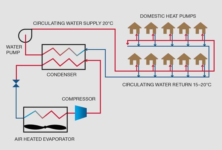
The overall scheme, as shown in Figure 1, shows a central air source heat pump warming water in a circulating loop. Consumers use individual heat pumps to extract heat from this to warm their properties. I have assessed the relative performance and found it to be similar or better than that of individual air source heat pumps. Advantages greatly outweigh disadvantages, especially in the longer term. The water loop introduces additional temperature drops and power consumption which reduce the COP of the system, but this can be more than offset by design features of the central unit. The simplest concept envisages uninsulated buried lines running close to ground temperatures. The central unit then consumes about 30% of the electrical load. If the underground lines are insulated the central unit can increase its contribution with gains in overall efficiency. The insulated water distribution system creates scope to develop incrementally from a system supplying very low-grade heat to a full district heating system. Each consumer would have the flexibility to use a heat pump and later a combination of direct heat exchange and heat pump or even just heat exchange to suit their property. They would have full flexibility to make stepwise improvements and could add air-conditioning using the same water circuit. Examination of the heat pump cycles reveals that the compression ratio and throughput vary considerably over the season. At very low air temperatures, single-stage units would require an excessive pressure ratio, and for this reason are not appropriate for properties with conventionally-sized radiators which need to run up to 60-70°C in the coldest weather.
Scroll compressors, the heart of heat pumps
The characteristics of scroll compressors, which form the heart of many small-scale heat pumps, are important when assessing performance and viability. They are used extensively in small- to medium-scale refrigeration applications where the temperature difference between source and sink is moderate and reasonably constant. They are favoured because of their simplicity, efficiency and low noise/vibration. Gas is trapped between the two scrolls in pockets. Relative movement of the scrolls transports the pockets from periphery to centre and the geometry progressively reduces the volume, hence compressing the pocket contents. Unlike other types of positive displacement compressor, they have no dead volume. The compression ratio and volumetric capacity are fixed. The efficiency at rated compression ratio and capacity is very high but space heating applications require a wide range of both capacity and pressure ratio. Heat pump systems work most efficiently if they run continuously and heat only to the temperature required. This contrasts with conventional gas boilers which raise water temperature to a fixed value and operate in start stop mode. Continuous operation minimises the temperature difference across the heat pump and this, being the denominator of the simple equation defining the COP, has a significant effect.
Heat pump systems work most efficiently if they run continuously and heat only to the temperature required. This contrasts with conventional gas boilers which raise water temperature to a fixed value and operate in start stop mode
Scroll compressor manufacturers have developed designs to overcome the fixed capacity and optimum pressure ratio limitations at the expense of complication and additional moving parts. To control capacity, a system which lifts the two scrolls apart in a short controllable cycle, temporarily breaking their seal, effectively switches off compression without stopping the compressor. Variable speed drives can also be used, but incur inverter losses. Systems have been developed whereby intermediate valved ports in the fixed scroll access the compression pockets partway through their trajectory. This allows compression ratio to be reduced in steps. Any system which reduces the required range of pressure ratios and capacities will enable simpler, more efficient compressors to be selected.
Detailed performance analysis
I compared the seasonal performance of the two-stage system with that of individual standalone heat pumps. Daily air temperatures from a nearby weather station (Exeter Airport) were taken for 1 Jan 2018-31 Dec 2018, the year of the so-called “Beast from the East” storm. These gave the heating degree days (HDDs) from which the heat duty of a typical house was determined. The seasonal performance of an air source heat pump was calculated using these figures and data for a proprietary heat pump. Carnot efficiency was calculated using the simple equation Thot/(Thot-Tcold). The proprietary data indicates that the actual efficiency is around 60% of Carnot efficiency for these small units. Each house was assumed to require 10 kW of heat delivered when air temperature is -15°C (HDD = 30.5°C). The performance of a system with 40 houses spaced along a 1 km road served by a water loop, heated by a central air source heat pump, was also calculated. The houses were assumed to be heated to 20°C, requiring water at a maximum temperature of 60°C with return from radiators 20°C cooler. When outside temperature is lower, the mean temperature of radiators is reduced, allowing for the theoretical reduction in heat transfer coefficient for free convection when differential temperature is lowered. Radiator water flows are maintained as this minimises supply temperature.
Air flows are also maintained so that air temperature drop across heat exchangers falls as load reduces. Heat transfer coefficients for these forced flow exchangers are assumed constant. The central water circuit can be set to have different supply and return temperatures. Initially, a fixed reduction of 5°C was chosen for the full load condition and water flow maintained at lower loads to maximise COP. Analysis showed that the flow should be modulated to save pumping power. A simple algorithm does this by making a rough tradeoff between water pumping power and COP improvement as load varies.
The calculation procedure allows all variables to be altered so that they can be optimised. Check calculations were done with hourly temperatures to see whether the diurnal variation would make average heat pump performance worse than that calculated from the daily HDDs. The room temperature target was lowered to 17°C for the night-time hours. The results, when averaged, showed little difference, giving confidence in the use of daily HDD.
I calculated the performance without imposing any of the limits to the operating envelope which apply to single-stage heat pumps. In practice these are likely to restrict application of single-stage air source systems to properties requiring a low maximum heating water temperature and/or with supplemental heating for very cold weather.
The properties of the refrigerant R401a were used to calculate the evaporator and condenser pressures in the heat pumps and hence the pressure ratio. This showed that the single-stage system will, at times, need very high pressure ratios even though the average daily temperatures for the chosen year chosen only dropped to -4.4°C, nowhere near the -15°C design minimum. The two-stage system has a much smaller spread of required pressure ratios.
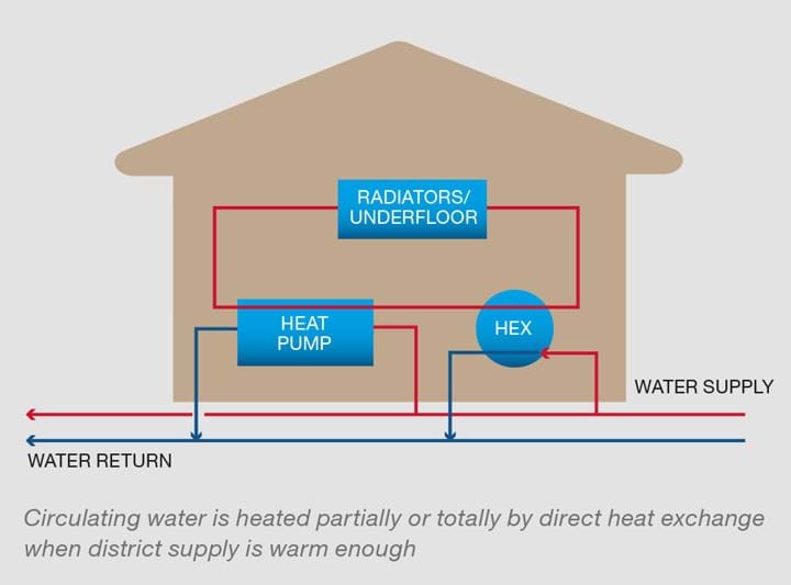
A base case with water supplied at +15°C was compared with cases having higher temperatures of +20°C and +30°C. The calculations allow for the house to use a direct heat exchanger and a heat pump in series when the water is hot enough to do some of the heating directly. This arrangement is illustrated in Figure 2.
Two key factors are the efficiency of the single units compared to that of the central unit. Results are based on single standalone units having 60% efficiency and the central unit 70%. The efficiency of domestic units in the two-stage system will improve because the required pressure ratios reduce. Values of 62, 63 and 65% were used respectively in the calculations for the three cases.
Lines were oversized to minimise pressure drop. Slightly larger pipes should add little to the cost of installation because this will be driven mainly by the expense of roadworks. Larger lines are also less likely to suffer damage. The optimum temperature drop at full capacity was found to be between 3°C and 5°C.
Results of comparison
The results of modelling a system of 400 kW maximum capacity supplying 40 houses with 10 Kw each spaced along a 1 km road served by a 6” pipe loop are summarised in Table 1.
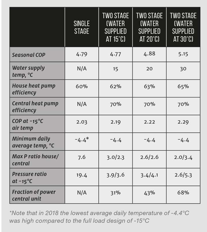
The results show that a slightly warm supply at 20°C gives an even split of compressor pressure ratios. Figure 3 shows the daily average pressure ratios needed, sorted in decreasing order over the year as well as the average daily temperature. It illustrates how a single-stage system would struggle to supply sufficiently hot water to radiators during the colder part of the year. This would be worse at night when temperatures are several degrees cooler than the average.
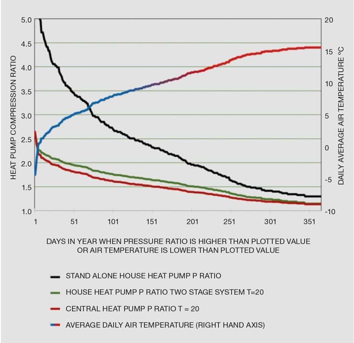
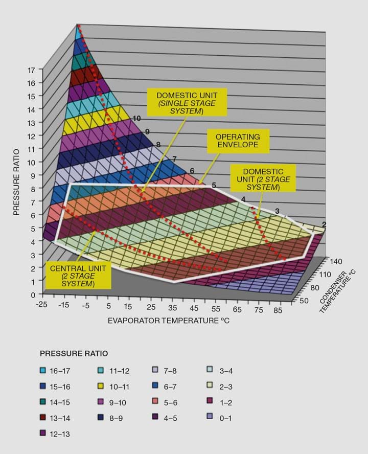
Figure 4 is a 3D-plot of the pressure ratios required for combinations of evaporator and condenser temperature for a system using R401a. Overlaid is the operating range for the compressor offered by a major manufacturer as well as the lines, dotted red, along which both the single- and two-stage system compressors would operate. This shows how far outside the envelope a single-stage system would be. The figure also shows that it would be appropriate to select different refrigerants for each stage of the two-stage system to allow compressors to operate in the central part of the envelope.
Other considerations
Installing this type of two-stage system will be disruptive and costly because an extensive new underground utility has to be laid. Locations have to be found for the central units far enough away from residential areas to avoid creating noise and vibration nuisance. In cities this could be a problem, although light industrial areas and sites used by other utilities might be available.
There are many advantages. Foremost is the ability to deploy highly efficient heat pump technology much more widely, greatly reducing the consumption of renewable electrical energy compared to that required for “green” hydrogen. Household heat pumps will no longer struggle to cope in very cold weather. The pipeline system has a very long life and allows a stepwise transition to accommodate improvements to the housing stock. Each locality can optimise its system to best suit its clients. Transition to a fully-centralised district heating utility is enabled while still allowing some users to boost temperatures with a heat pump. The nightmare of many individual poorly-maintained, noisy air source evaporators is avoided. The problem of individual units freezing is eliminated as the central units can employ industrial methods for the defrost cycle. The compressors in household heat pumps can be simpler and thus more reliable as they will be designed for a lower range of pressure ratios and capacities. The most obvious owners for the central system are the utility companies supplying the electricity. It would become a key fifth utility after power, water, gas and data – all essential to operate efficiently in the zero-carbon future.
Where next?
A two-stage centralised yet localised air source heat pumping system has been described here. It has performance equal to and potentially better than individual household heat pumps. It provides the infrastructure needed for transition towards a highly efficient district heating system. The concept uses far less renewable electrical energy than needed by the sustainable alternatives of “green” hydrogen or direct electrical power.
I spent nine years of my “retirement” working for the IEA Greenhouse Gas R&D programme, hence my great interest in climate abatement technologies. Our local and county councils are declaring climate emergencies and are beginning to take concrete action to reduce their own emissions. Hopefully, it is only a matter of time before they start to support actions in the wider community perhaps through exercise of stronger planning powers. However, energy utilities and developers are better placed to trial and develop this type of energy system. All parties will need to work together to be able to implement the best and most sustainable systems for heating our homes and businesses.
Do fellow chemical engineers have views on aspects of this article or ideas on how the concept could be developed? I would be most interested to hear your views at mhainescofreetech@btinternet.com.

Recent Editions
Catch up on the latest news, views and jobs from The Chemical Engineer. Below are the four latest issues. View a wider selection of the archive from within the Magazine section of this site.


